5-26 Troubleshooting Charts: Secure Hardware Failure
5.9 Secure Hardware Failure
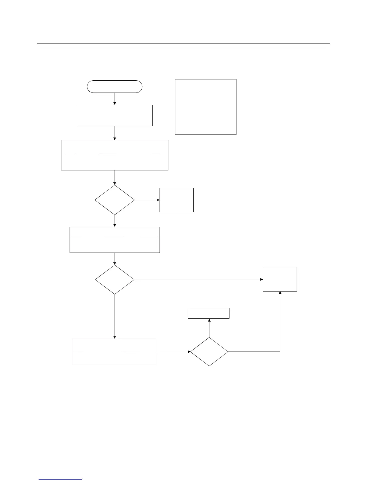
09/10 or 09/90
Secure Hardware Failure
Use an ohmmeter to electrically verify the following secure related
signals on the controller board and the Vdd levels:
Signal
Probe Point Level
VDD_IOP R2509 1.875V
VDD_IOM R2511 1.875V
VDDC R2512 1.875V
Are voltage levels
correct?
Repair DC Voltage
Regulators
No
Yes
Synopsis
This failure relates only to secure
equipped radios and indicates a power
up self test failure for the secure
circuitry. More specifically this failure
indicates a failure in communications
between the DSP and the secure
circuitry. The secure circuitry is not
considered to be field repairable so
troubleshooting is limited to verifying a
problem with the secure circuitry and
replacing the controller if required.
Use an oscilloscope to verify clocks on main board:
Signal
Probe Point Frequency
MACE CLOCK R6113 4 MHz
OPT_SSI_CLK R6170 1.5 MHz
OPT_SSI_FSYNC R2513 8 KHz
Are signals correct?
No
Check SSI clock
signals from CPLD
and repair circuitry
Yes
Make sure the radio is fully assembled. These
errors will occur if the Main boards are
not properly assembled. Also note a battery
removal and reattachment is needed after a
“Secure HW Upgrade” to clear errors.
Examine data validity
Are data signals
present?
Yes
Use an oscilloscope to verify activity on Main board :
Signal
Probe Point
SSI_MACE_DIN R6118
No

 Loading...


