Theory of Operation: Bluetooth 3-55
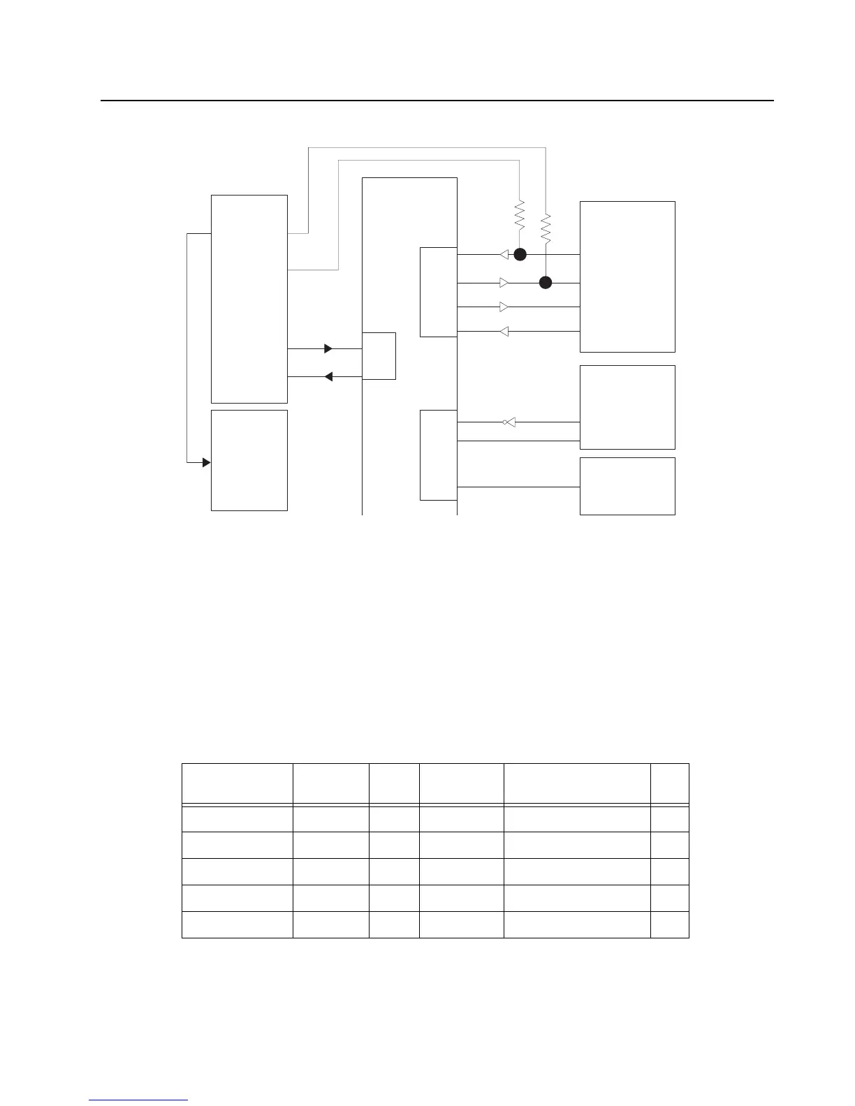
Figure 3-45. Bluetooth LF UART Connection Block Diagram
The Bluetooth IC shutdown (U2415 pin L3) and wakeup (U2415 pin K3) pins are also connected to
the host controller. A Bluetooth PTT pin on the host controller (U2415 pin J2) tells the OMAP (U6302
pin Y5) when the user pressed the PTT button on the Bluetooth accessory. As the BT IC I/O is 1.8V,
but the host controller I/O is 3.3V, level shifters are employed for interconnection between the two.
The host processor IC is connected to the LF receiver IC by a four-wire SPI bus. This SPI bus also
communicates with an on-board accelerometer. The LF transmitter circuit uses a 125 kHz signal
(U2415 pin M3) that is turned on and off (OOK) by the USART1_TX signal (U2415 pin L12).
Table 3-13. SPI I/O
Signal Name Pad Name GPIO MUX
Function
Schematic Name I/O
SPIP – NPCS[2] PA09 9 B SPIO_CS2 O
SPIP – NPCS[0] PA10 10 A NFC_CS O
SPIP – MISO PA11 11 A SPIO_MISO I
SPIP – MOSI PA12 12 A SPIO_MOSI O
SPIP – SCK PA13 13 A SPIO_CLK O
TI NL 5500
Bluetooth/GPS
ATMEL AVR32
AT32UC3A0512
Low Frequency
Receiver AS3930
DAT
CL_DAT
LF Transmit
(OR Gate)
HCI_TX
USART0
USART1
USART2
Debug RX
Debug TX
BT Debug
Flex
J2401 Connector
PB29
K6
Pin 33
Pin 34
Pin 25
Pin 26
K7
PB30
PA00
PA01
PA03
PA04
PA05
PA07
PA06
A4
B5
B4
B7
9
10
J6
H6
J7
J8
K11
J10
L12
HCI_RX
HCI_CTS
HCI_RTS

 Loading...


