9-6 Debugging Fixture: Board Assembly on Debugging Fixture
9.6 Board Assembly on Debugging Fixture
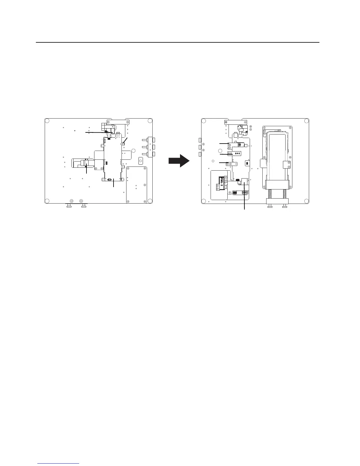
1. Turn the fixture to the bottom plane and assemble the RF board on the fixture, then secure it
by turning the PCB clamp. Connect the NFC flex connector and the extended flex connector
to the RF board.
2. Turn the fixture to the front side and connect the connector on the debugging flex to the RF
board connector. Ensure that the heat sink press plate is touching the thermal pad . Ensure
the power connection bracket is pressing the battery contact and ensure the press pin is
pressing on the temper switch.
Figure 9-10. Board assembly
RF Board
Extended Main Flex
(0104055J18)
NFC Flex
(0104052J74)
Heat Sink
Press Plate
Power
Connection
Bracket
Press
Pin
Debug Flex
(0104055J17)
PCB Clamp

 Loading...


