3-54 Theory of Operation: Bluetooth
3.5.2 Bluetooth Clocks
The Bluetooth IC requires a 26 MHz TCXO (Y1304, TCXO_CLK) for the core and a 32.768 kHz
(U6101 pin E2 on Main Board, RTC_CLK) slow clock for the USART. This is the same clock used for
the GPS portion of the BT/GPS combination IC.
The host processor IC requires a 12 MHz crystal oscillator (Y2475) clock. The LF receiver IC
requires a 32.768 kHz (U6101 pin E2 on Main Board, RTC_CLK) clock.
3.5.3 Bluetooth I/Os.
The communication between the Bluetooth IC and the host controller is by a four-wire HCI USART0
bus (RX, TX, CTS, RTS). The Bluetooth IC receives a firmware update over the USART0 each time
it is powered on. The LF receiver IC transmits its data over the USART1. USART2 is used for
displaying debugging messages.
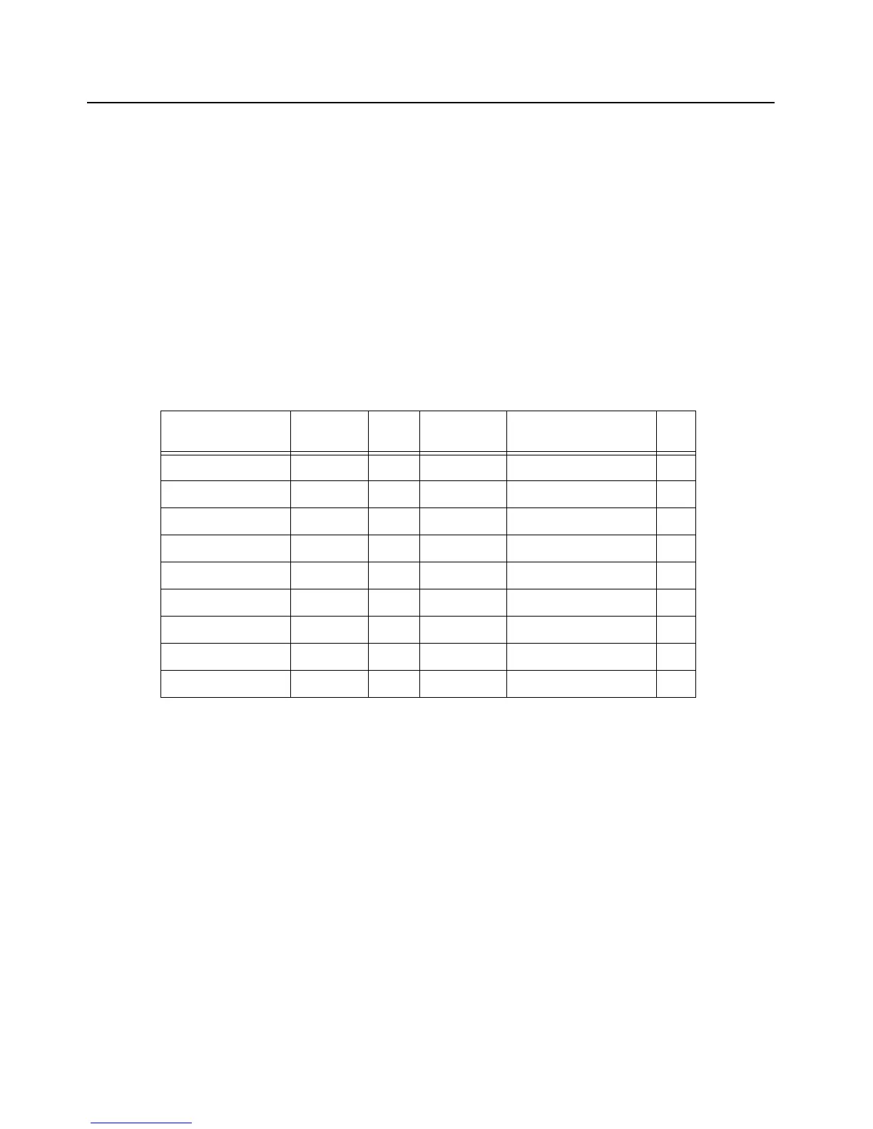
Table 3-12. Bluetooth Host Processor UART I/O
Signal Name Pad Name GPIO MUX
Function
Schematic Name I/O
USART0 – RXD PA00 0 A BT_UART_TX_3.3V I
USART0 – TXD PA01 1 A BT_UART_RX_3.3V O
USART0 – RTS PA03 3 A BT_UART_CTS_3.3V O
USART0 – CTS PA04 4 A BT_UART_RTS_3.3V I
USART1 – RXD PA05 5 A USART1_RX I
USART1 – TXD PA06 6 A USART1_TX O
USART1 – CLK PA07 7 A USART1_CLK I
USART2 – RXD PB29 61 A AVR_USART2_RX I
USART2 – TXD PB30 62 A AVR_USART2_TX O

 Loading...


