Theory of Operation: Main Board 3-3
3.1 Main Board
The main board performs the transmitter and receiver functions necessary to translate between
voice and data to modulated radio-frequency (RF) carrier at the antenna. The main board contains
all the radio’s RF circuits for the following major components:
• Receiver
• Transmitter
• Frequency Generation Unit (FGU)
• Controller
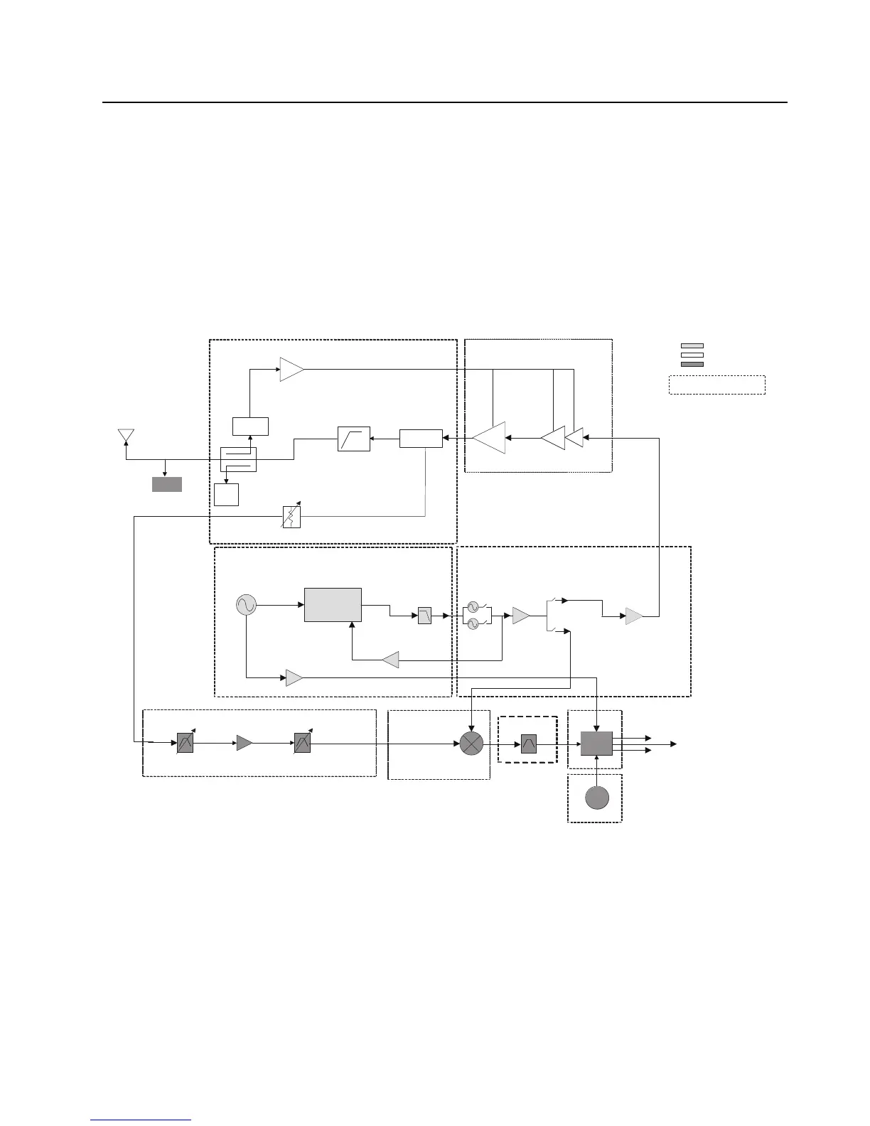
Figure 3-2, Figure 3-3 and Figure 3-4 illustrates the UHF1, UHF2, VHF and 700/800 MHz transceiver
block diagrams.
Figure 3-2. Transceiver (UHF1/ UHF2) Block Diagram (Power and Control Omitted)
FGU
Transmitter
Receiver
2nd
LO
Digital
RF Atten
Antenna Switch
coupler
Rev
Power
Detector
Log
Amp
FET
TRIDENT IC
LOOP
FILTER
PRESCALAR
BUFFER
RX SSI Data
16.8MHz
BUFFER
PRE
BUFFER
TX LO
TX
BUFFER
TX
RX
*
16.8MHz
RX SSI Clock
RX SSI Frame Sync
Indicates Sub-shield
Harmonic
Filter
Driver
Amplifier
*
Abacus
IF Filter
15dB Step Attn
RX VCO
TX VCO
UHF1/ UHF2
LNA
UHF1/ UHF2
Mixer
GPS

 Loading...


