Troubleshooting Charts: RX RF Failure 5-29
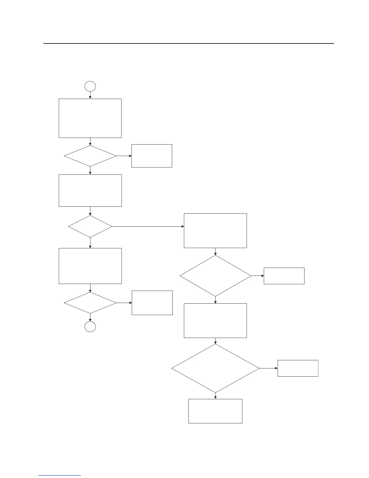
RX RF Failure – Page 3
2
Remove shield, SH9.
Measure RF levels at first
preselector filter and
compute filter loss.
UHF1/UHF2: Input side of
C1935 & output side of C1939.
VHF: Input side of C330
& output side of C339.
Loss < 3 dB?
Check components
and replace
defective parts.
Autotune the radio.
No
Measure RF levels at LNA
and compute LNA gain.
UHF1/UHF2: Input side of
C1931 and output side of C1936.
VHF: Input side of C339 and
output side of C360.
Gain about
15 dB?
Check LNA:
Check DC bias voltages of
UHF1/UHF2: U1932 at the
base (pin 1) & collector (pin 3).
VHF: U304 at the base
(pin 1) & collector (pin 3).
No
Is base voltage =
0.787 V?
Collector voltage =
1.56 V?
Replace
UHF1/UHF2: U1932
VHF: U304
Is base voltage =
1.022 V? Collector
voltage = 0.787 V?
Emitter voltage =
1.561 V?
Replace
UHF1/UHF2: Q1922
VHF: Q303
Check DC input line
voltages and visually
inspect and replace
defective components if
needed.
No
Yes
No
Yes
Measure RF levels at second
preselector filter and compute
filter loss.
UHF1/UHF2: input side of
VHF: input side of C345 & output
side of C357.
C1959 & output side of C1961.
Loss < 4 dB?
Check components
and replace
defective parts.
Autotune the radio.
No
Yes
5
Yes
Yes
Check DC bias voltages of
UHF1/UHF2: Q1922 at the base
(pin 2 or 5), collector (pin 3)
& emitter (pin 4).
VHF: Q303 at the base
(pin 2 or 5), collector (pin 3)
& emitter (pin 4).
Note: RF Test frequency used:
UHF1: 424.975MHz
700: 769.0625MHz
UHF2: 485.075MHz
VHF: Input side of C330 & output side of C339.
800: 860.0625MHz
Measured with a High Frequency Probe for relative comparisons and troubleshooting only.
Actual S21 gain or loss may differ if the test point is not 50 ohms.

 Loading...


