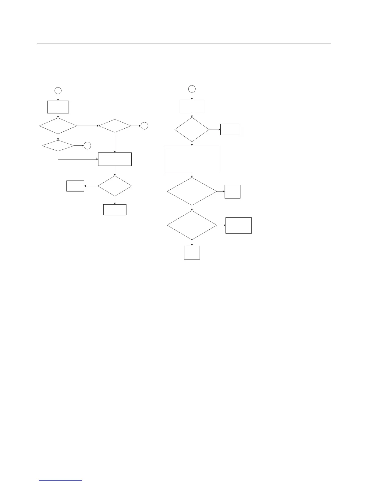
9
Clock
Synthesizer
Measure tuning
voltage (Vt) at
R608
CLK_SSI_RX
< 1.2 MHz?
Vt = 3 Vdc?
10
Vt = 0 Vdc?
10
Remove SH11 , inspect
clock oscillator circuit at
U601-19,20
Visual
examination
Replace Varactor
VR601
Repair
Defects
No
No
No
Yes
Yes
Yes
No
10
Remove SH11,
inspect
components
Visual
examination
OK?
Check level shifters, U603 and U604 by
checking signal amplitudes using an
oscilloscope at R616, R617, R618. R616
and R617 belong to U603 and R618
belongs to U604. Note: These resistors
are not placed. You will be probing the
pads.
Repair
defects
No
Yes
Yes
Is the input side
pad of R616,
R617 & R618 = 3
V?
Is the output side
pad of R616,
R617 & R618 =
1.875 V?
Replace
Abacus,
U601
Replace level
shifters, either
U603, U604 or
both.
Replace
Abacus,
U601
No
Yes
No
Yes
Note: RF Test frequency used:
UHF1: 424.975MHz
UHF2: 485.075MHz
VHF: 154.275MHz
700: 769.0625MHz
800: 860.0625MHz
Measured with a High Frequency Probe for relative comparisons and troubleshooting
only. Actual S21 gain or loss may differ if the test point is not 50 ohms.

 Loading...


