MN000770A01-AA July 30, 2014
Chapter 5 APX Dual-Radio Installation
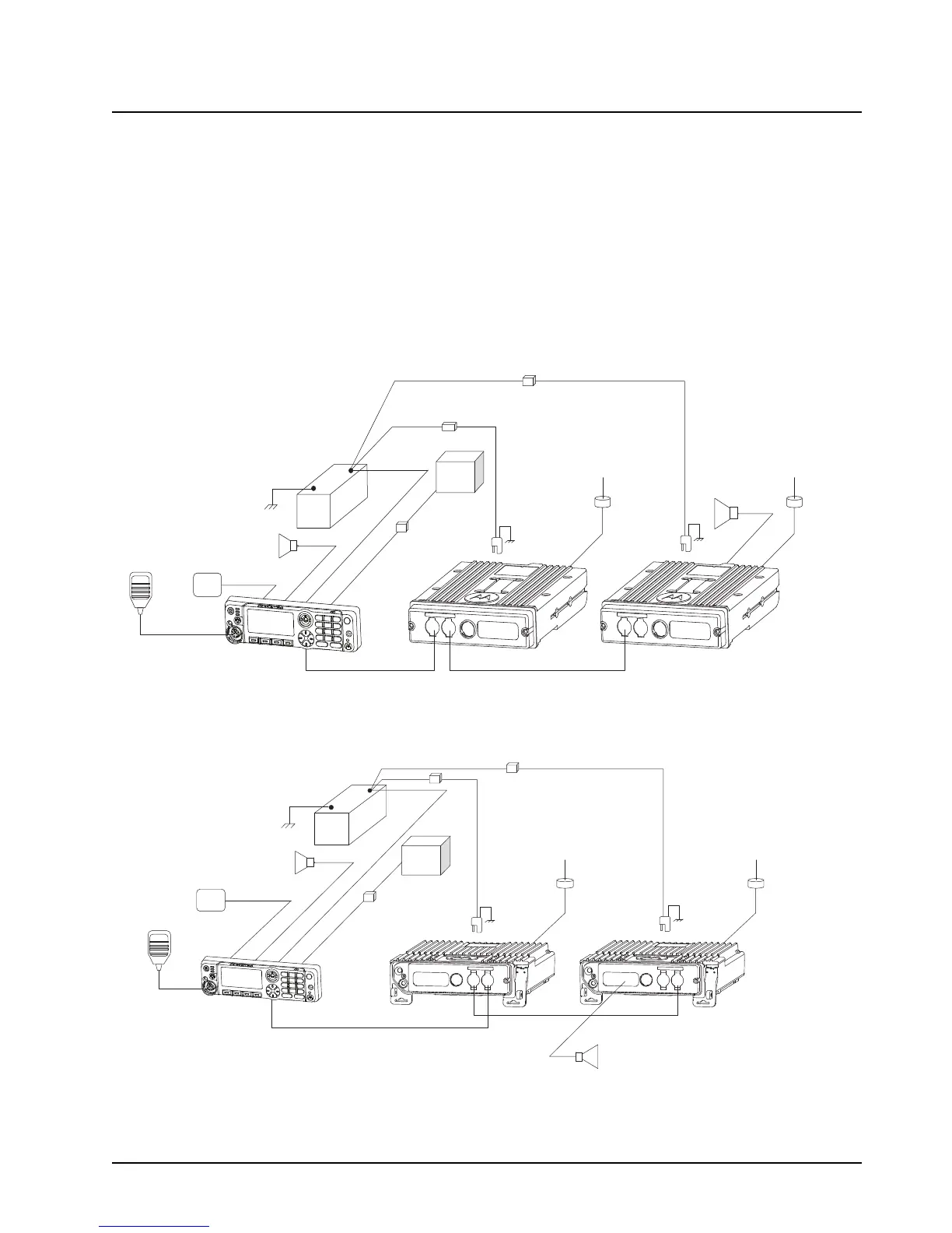
5.1 Installation Planning
The ASTRO APX Mobile Dual-Radio System consists of several different components
(see Figure 5-1 and Figure 5-2), and some preliminary planning should be completed before
beginning actual system installation. The O7 Control Head, emergency footswitch, and speakers
mount in the operator’s compartment. It is recommended that the radios be mounted in the vehicle’s
trunk. Be sure the chosen locations for all housings do not expose the units to dirt or moisture.
Figure 5-1. Side By Side Installation For APX Mobile Mid-Power Dual-Radio O7 Control Head System
Figure 5-2. Side By Side Installation For APX Mobile High-Power Dual-Radio O7 Control Head System
SPEAKER 1
(-)
(+)
BATTERY
ANTENNA
SPEAKER 2
SECONDARY
RADIO
PRIMARY
RADIO
EMERGENCY
FOOT SWITCH
07 CONTROL
HEAD
MIC
FUSE
FUSE
FUSE
BLOCK
FUSE
IGNITION LEAD
ANTENNA
DC POWER
CABLE
DC POWER
CABLE
(-)
(+)
BATTERY
SPEAKER 1
FUSE
FUSE
BLOCK
ANTENNA
ANTENNA
SPEAKER 2
PRIMARY
RADIO
SECONDARY
RADIO
EMERGENCY
FOOT SWITCH
07 CONTROL
HEAD
FUSE
FUSE
MIC
IGNITION LEAD
DC POWER
CABLE
DC POWER
CABLE
 Loading...