July 30, 2014 MN000770A01-AA
5-4 APX Dual-Radio Installation: Trunk Units
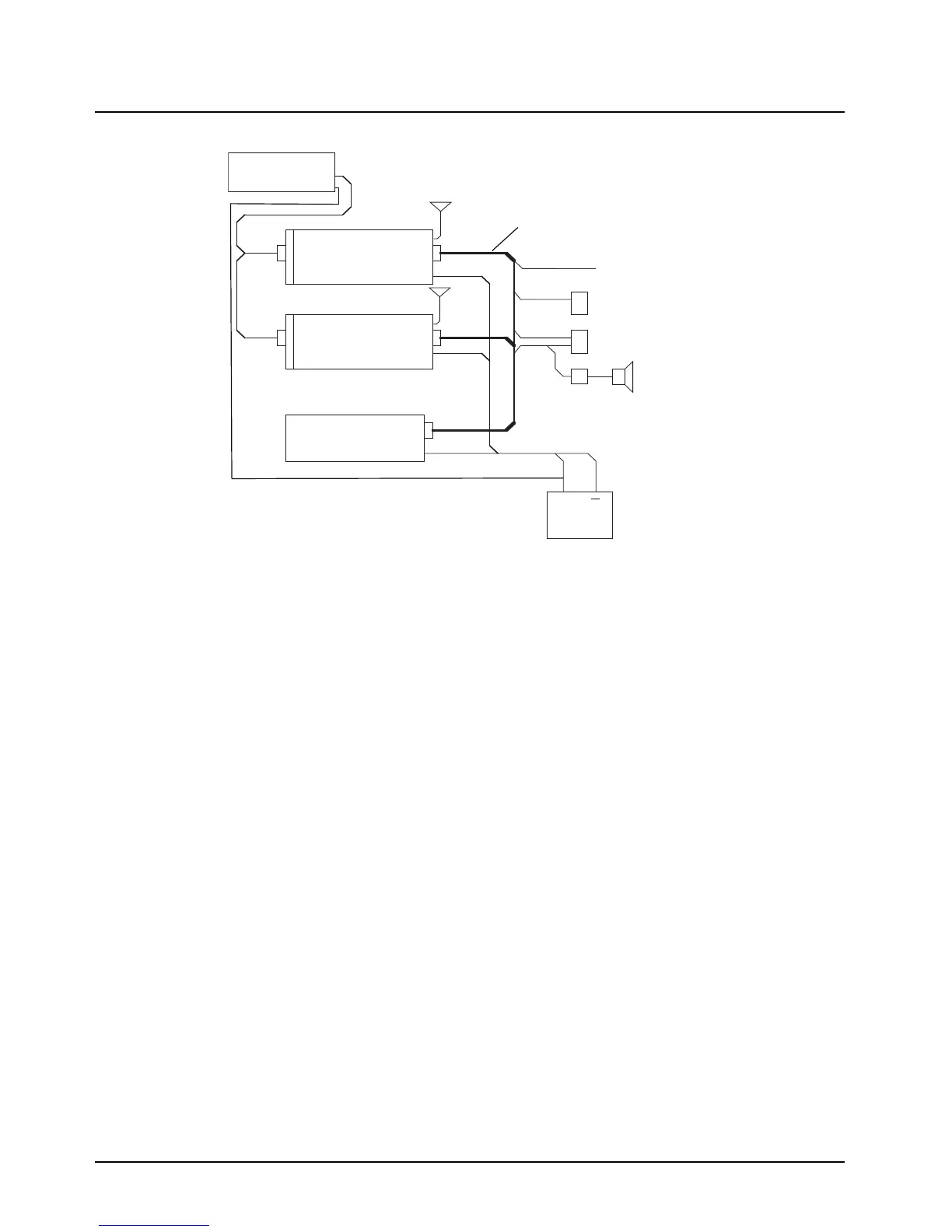
Figure 5-4. APX Mobile Mid-Power Dual-Radio, Dual-Radio Combined Audio Configuration
5.2.2 Cables
This section describes the APX Dual-Radio System cables installation.
5.2.2.1 APX Dual-Radio Cables
The APX Dual-Radio Cable (P/N HKN6250_) connects the Primary and Secondary radios to the O7
Control Head via the quick-disconnect connector. Attach the yellow radio connector end of the APX
Dual-Radio Cable, to the front left of the Primary Radio (female connector, labeled “Control Unit”).
Securely tighten the two screws. Attach the red radio connector end of the cable to the front left of
the Secondary Radio (female connector, labeled “Control Unit”). Securely tighten these two screws
as well. The quick-disconnect end of the APX Dual-Radio Cable will attach to the O7 Control Head,
and is mounted in the operator’s compartment. This end of the cable also contains the connections
for the speakers, the emergency foot switch, and the ignition sense.
5.2.2.2 Power and Ground Cables
Route the red Radio Power Cables from both radios to the vehicle’s battery compartment, using
accepted industry methods and standards. It is important that both power leads are connected to the
battery, rather than using one power lead through the vehicle and splitting it to both radios. This is
because it is possible to have both mobile radios transmit at the same time (OTAR and data), and
the power cable for each radio is rated to handle the maximum transmit current of that radio only.
Both radios must connect to the same battery, to prevent cranking problem.
Be sure to grommet the firewall hole to protect the cable. Remove the 15-amp (P/N 6580283E06) or
20-amp (P/N 6580283E07) fuse from the fuseholder and connect the red lead of the Radio Power
Cable to the positive battery terminal using the hardware provided as shown in Figure 5-5. Connect
the black lead to a convenient solid chassis ground point. DO NOT connect the black lead directly to
the battery’s negative terminal.
Ignition
Emerg
Headset
Primary Radio
Secondary Radio
Audio Combiner
Battery
RF
Combined
Audio
+
Dual Radio Accessory Cable, HKN6250_
Motorcycle
Control Head
RF
 Loading...