July 30, 2014 MN000770A01-AA
5-6 APX Dual-Radio Installation: Installation Considerations
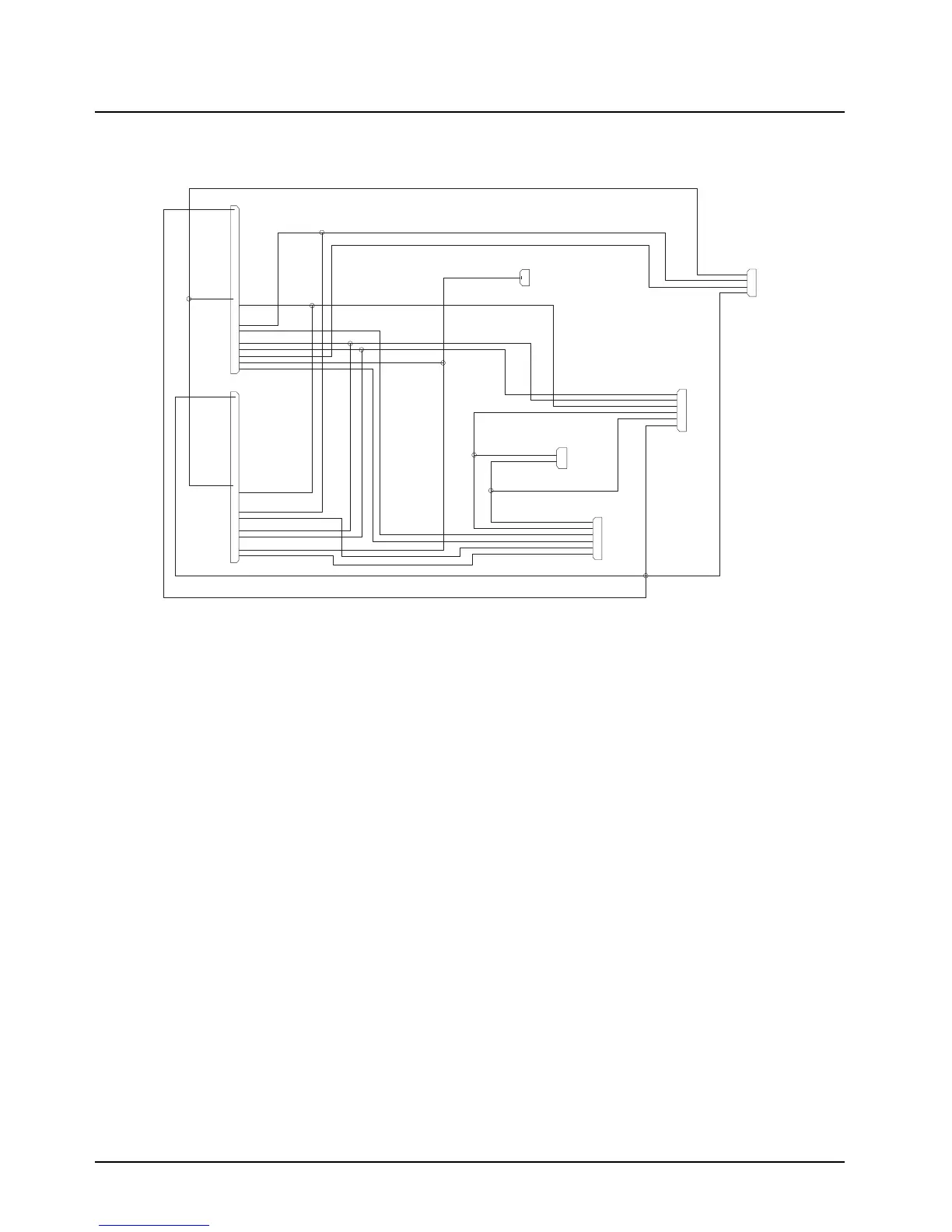
5.2.2.4 Dual-Radio Accessory Cable
Refer to Figure 5-6, for the Dual-Radio Accessory Cable (P/N HKN6250_), diagram.
Figure 5-6. Dual-Radio Accessory Cable Diagram
5.3 Installation Considerations
Be aware of the following installation considerations:
1. Turn the vehicle’s ignition switch off during installation.
2. Connect both black leads to the same vehicle chassis point. This prevents possible ground
loop damage to the system should the ground point become bad.
3. Locate all fuses near the battery or the ignition.
5.4 Power Connections
Do the following:
1. Route the orange fused lead to the ignition voltage or battery voltage (see Section 5.2.2.3,
"Ignition Cable").
2. Route the red fused lead from each radio directly to battery positive.
3. Connect the black lead from each radio to the vehicle chassis.
5.5 APX Dual-Radio O7 Control Head Cable
Refer to Figure 5-5, the APX Dual-Radio Cable (P/N HKN6250_) cable connects the O7 Control
Head kit (P/N PMN1035_), to the dual remote radios via the quick-disconnect.
NOTE: Follow standard installation practices when routing and connecting all system cables. Use
labels to identify both ends of each cable and make sure that all connections are electrically
sound. Be sure that cables are secure and not routed or lying where they can be snagged,
cut, or crushed.
SAI
EMER_1
EMER_2
PTT-1
HORN-LGTS-1
HORN-LGTS
SWB+
EMER
PTT
IGNITION
IGNITION-1
MIC
HUB
SA2
SPKR-CONI-2
SPKR-1
SPKR-2
SA7
SA6
SA8
SA9
SA5
SA4
HUB-1
MIC-1
PTT-2
IGNITION-2
RD-SPK-H1
RD-SPK-L0
GN-SPK-L0
GN-SPK-H1
SPKR-CON1-1
SPKR-CON2-1
SPKR-CON2-2
SA3
GROUND
1
2
6
4
5
1
2
3
1
3
4
2
GROUND-3
1
4
3
6
2
5
GROUND-2
GROUND-1
HUB-2
HORN-LGTS-2
MIC-2
P1
P2
1
2
3
4
5
6
7
8
9
10
11
12
13
14
15
16
17
18
19
20
21
22
23
24
25
26
1
2
3
4
5
6
7
8
9
10
11
12
13
14
15
16
17
18
19
20
21
22
23
24
25
26
P4
P7
P5
P6
P3
 Loading...