List of Figures vii
MN000770A01-AA July 30, 2014
List of Figures
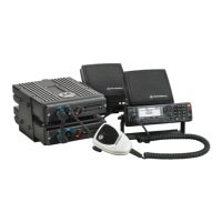
Figure 2-1. APX Mobile Dual-Radio System Cabling Interconnect Diagram For O7 Remote Mount ......2-1
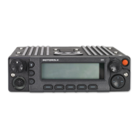
Figure 2-2. O7 Control Head....................................................................................................................2-2
Figure 2-3. Primary Radio Selected Diagram ..........................................................................................2-8
Figure 2-4. Secondary Radio Selected Diagram .....................................................................................2-8
Figure 3-1. Enabling the APX Dual-Radio as Primary or Secondary Radio ............................................3-1
Figure 3-2. APX Dual-Radio Emergency Mode Operation Configuration ................................................3-3
Figure 3-3. Secondary Radio Talkgroup Mute Operation Configuration ..................................................3-4
Figure 3-4. Enabling Secondary Radio Transmission..............................................................................3-5
Figure 3-5. Cross Band Mute Operation Configuration............................................................................3-5
Figure 3-6. Enabling Fixed Swap Menu...................................................................................................3-6
Figure 3-7. Menu Swap Configuration .....................................................................................................3-6
Figure 5-1. Side By Side Installation For APX Mobile Mid-Power Dual-Radio
O7 Control Head System.......................................................................................................5-1
Figure 5-2. Side By Side Installation For APX Mobile High-Power Dual-Radio
O7 Control Head System.......................................................................................................5-1
Figure 5-3. Stack Mount Installation For APX Mobile Mid-Power Dual-Radio
O7 Control Head System.......................................................................................................5-3
Figure 5-4. APX Mobile Mid-Power Dual-Radio, Dual-Radio Combined Audio Configuration.................5-4
Figure 5-5. APX Mobile Dual-Radio System Cabling Interconnect Diagram For O7 Remote Mount ......5-5
Figure 5-6. Dual-Radio Accessory Cable Diagram .................................................................................5-6
 Loading...