February 3, 2003 6881076C20-E
9-6 Basic Troubleshooting: Transmitter Troubleshooting
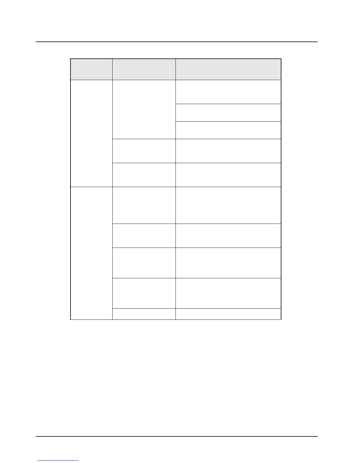
No Modulation VCO Board 1. All modulation testing should be done
with the radio keyed and 1Vrms on the
microphone high line of the microphone.
2. Is radio properly tuned? (See Chapter
6. Radio Alignment Procedure.)
3. Is there > 400 mVrms at J500 pin 11?
If so, replace the VCO board.
Command Board If there is > 400 mVrms (ac coupled) at
P501 pin 49 and not at J500 pin 11,
replace the command board.
VOCON Board If there is >200 mVrms modulation at J501
pin 39 and no modulation at J501 pin 49,
replace the VOCON board.
Distorted
Modulation
Bandwidth Is the correct bandwidth selected (use the
appropriate radio programming software)?
Is radio properly tuned?
(See
Chapter 6: Radio Alignment
Procedure
.)
Compensation Not Set/
Working
(DPL Distorted)
Check compensation setting.
If compensation won’t adjust, go to Can’t
Set Compensation below.
VOCON Board With 80 mVrms on the mic high line, is the
signal on pin 49 of P501 distorted (ac
coupled)?
If so, replace the VOCON board.
Command Board With 80 mVrms on the mic high line, is the
output of the command board VCO Mod
(pin 11 of J500) distorted?
If so, replace the command board.
VCO Board Replace VCO board.
Table 9-5. Transmitter Troubleshooting Chart (Continued)
Symptom Possible Cause
Correction or Test (Measurements
Taken at Room Temperature)

 Loading...


