6881076C20-E February 3, 2003
Basic Troubleshooting: Transmitter Troubleshooting 9-7
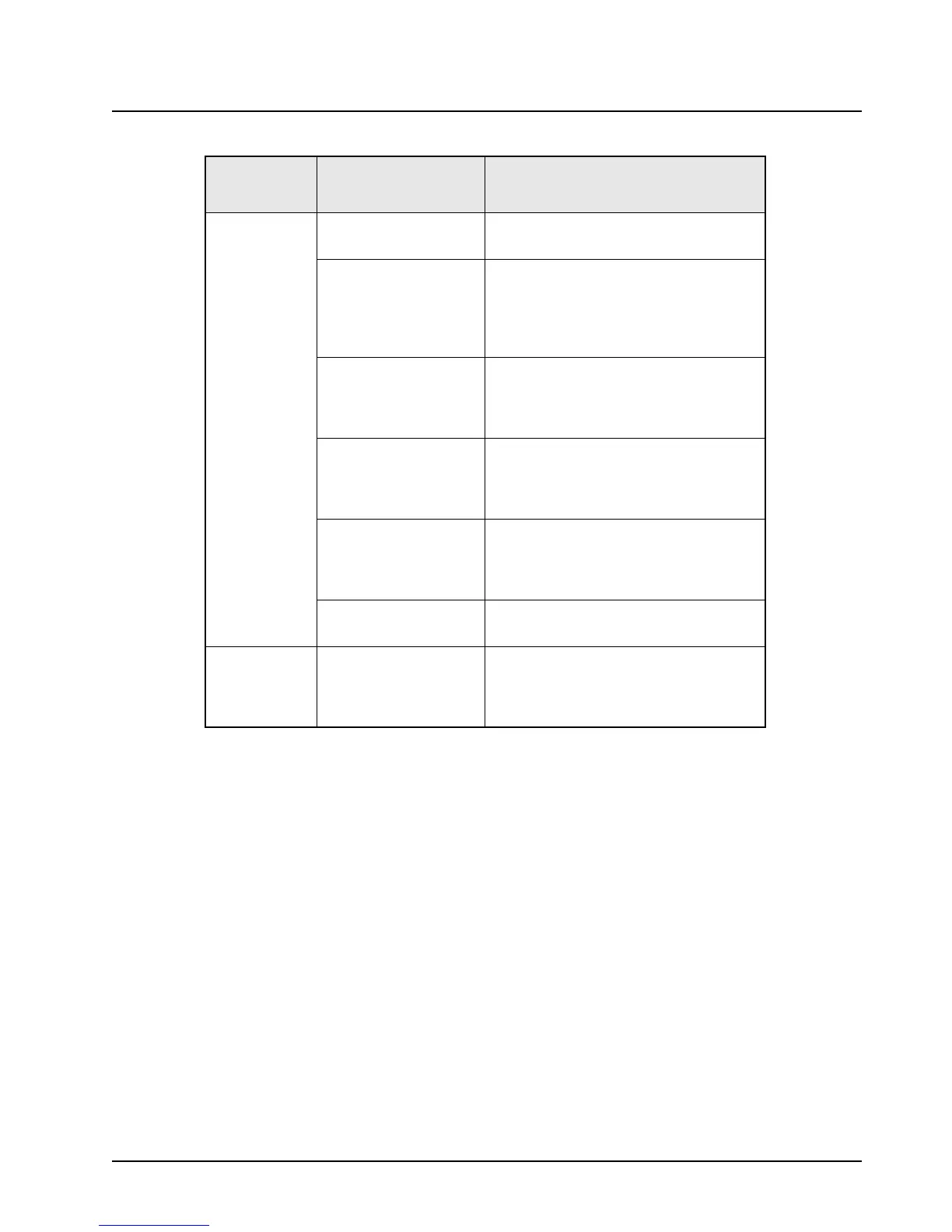
Bad
Microphone
Sensitivity
Check Deviation and
Compensation
Retune, if necessary.
Microphone Speak loudly into the microphone while
monitoring the microphone line (pin 6 of
P502).
If it is not >80 mVrms, then replace the
microphone.
Command Board With 80 mVrms on the mic high line, check
pin 39 of P501.
If not >100 mVrms (ac coupled), replace
the command board.
VOCON Board With 80 mVrms on the mic high line, check
pin 49 of P501.
If not >100 mVrms (ac coupled), replace
the VOCON board.
Command Board With 80 mVrms on the mic high line,
monitor the VCO mod line (pin 11 on
J500). Voltage should be >200 mVrms.
If not, replace the command board.
VCO Board If correct voltage was found on pin 11 of
J500, replace the VCO board.
No/Low
signaling (PL,
DPL, Trunking,
MDC)
Check Programming Reprogram codeplug.
Table 9-5. Transmitter Troubleshooting Chart (Continued)
Symptom Possible Cause
Correction or Test (Measurements
Taken at Room Temperature)

 Loading...


