5-6 Radio Programming and Tuning: Transmitter Alignment Options
8. Repeat steps 4–6 for the remaining test frequencies (F2–F5).
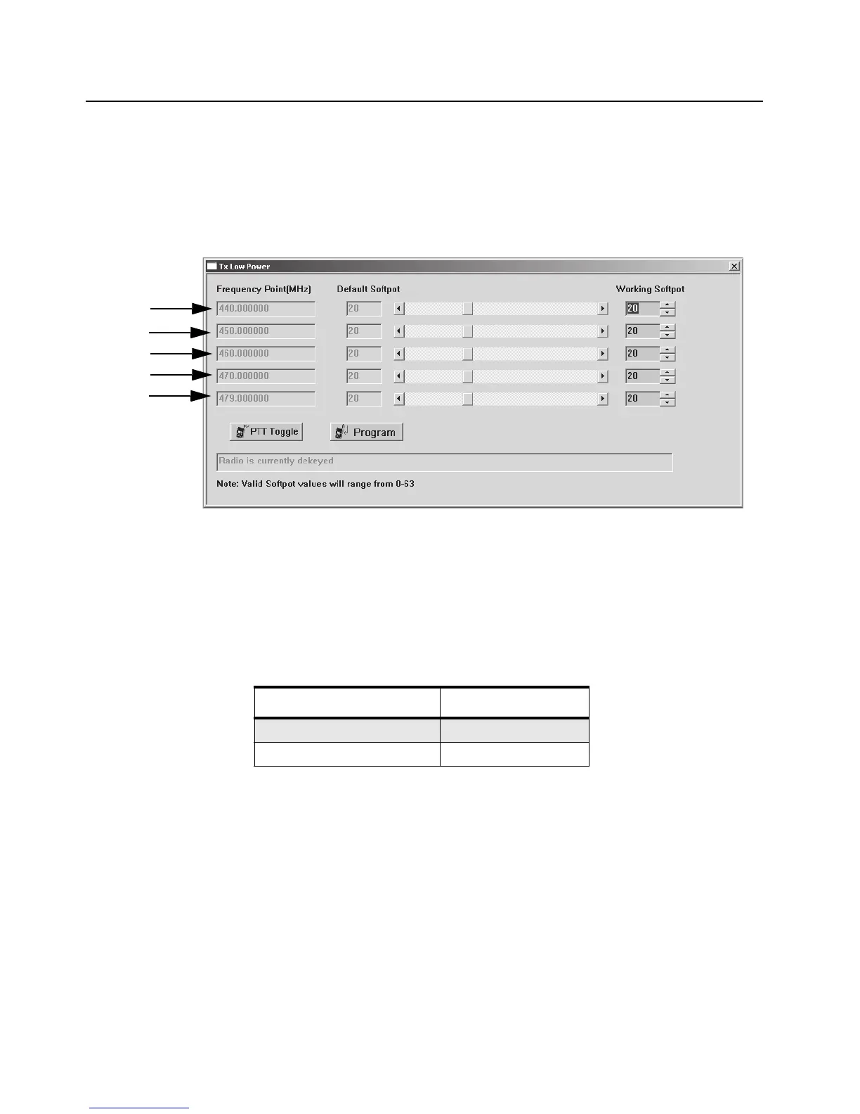
9. Press Program to commit the softpot values into the codeplug.
10. Exit the Transmit Low Power function.
11. Proceed to Adjust Modulation.
5.5.3 Transmit Modulation Tuning
There are 2 variations of Transmit Modulation Tuning, namely 12.5 kHz and 25 kHz.
Table 5-3. Transmit Modulation Tuning
5.5.3.1 Service Monitor Setting
1. Initial setup using the 8920A RF Communications Test Set
a. Connect “RF IN/OUT” port on 8920A to RF adaptor on radio’s antenna port using a N-Type to
BNC cable. Connect “AUDIO OUT” on 8920A to “Tx MOD” on test box using a BNC to BNC
cable. Connect the rest according to Figure 5-2. Radio Tuning Setup.
b. On 8920A, select “Tx” under “SCREEN CONTROL”.
c. Using the “CURSOR CONTROL”, key in the following items:
i. Tune Mode: Auto
ii. Tune Freq: Depends on Tune Mode
-Once “Auto” is selected, the centre frequency is set to the strongest RF signal
-Once “Manual” is selected, desired frequency has to be entered manually
Figure 5-4. Tx Low Power Window (Low Power)
Channel Spacing (kHz) Tuning Range (kHz)
12.5 2.25 ± 0.05
25 4.5 ± 0.1
F1
F2
F3
F4
F5

 Loading...