7-10 Maintenance – Non Keypad Model: Disassembling and Reassembling the Radio
f. Push the latches on the Front Circuit Board (36) sideways to the right to release the
flexible cable from the connector. (Refer Figure 7-7).
7.5.1.2 Chassis Assembly Disassembly
1. Remove the Accessory Bracket (31).
2. Remove the nut (14) on the On/Off Volume Knob Shaft and Channel Knob Shaft with the Crab
Eye Nut Opener.
3. Remove the screw holding the Sub Circuit Board (13) to the Chassis (23) with a Phillips
screwdriver.
4. Push the latches on the Main Circuit Board (16) to release the Flexible Cable (34) from the
connector.
5. Remove the Sub Circuit Board from the Chassis. (Refer Figure 7-8).
6. Remove the six screws (33) holding the Main Circuit Board to the Chassis with a Phillips
screwdriver. Remove the RF Support Screw (17) with a flat head screwdriver.
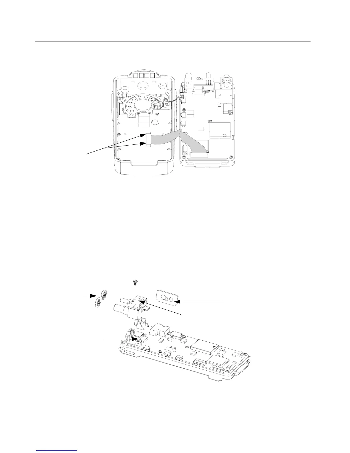
Figure 7-7. Unlatch the Flexible Cable
Figure 7-8. Sub-Circuit Board and Accessory Bracket Removal
Latches
Nuts
Accessory Bracket
Sub Circuit Board
Latch

 Loading...