Option Board Installation 3-13
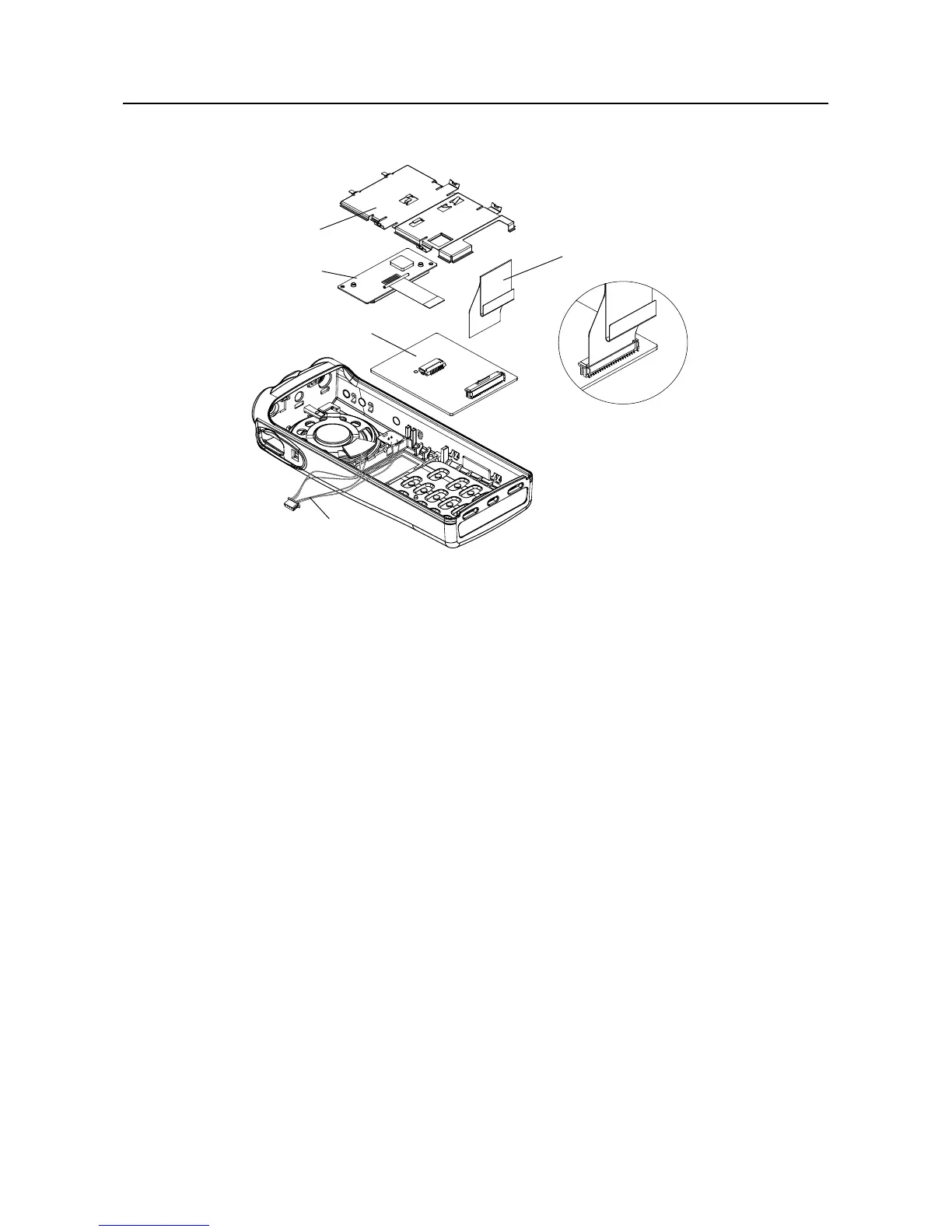
4. Reassemble the option board to the front cover assembly.
5. Insert the display ßex circuit into the connector on the option board.
6. Insert the jumper ßex circuit into the connector on the option board. Notice the orientation of
the ßex circuit. Arrows on the jumper ßex point to the correct way of inserting the ßex into the
connector.
7. Replace the retainer by placing the two top hooks into the slots below the speaker in the front
cover; then, pivot the retainer into the front cover. Ensure that all four tab arms snap correctly
into the front cover.
8. With the keypad option board and retainer correctly in place, the front cover assembly can
now be reassembled as described in paragraph 6.6.
Figure 3-12 Changing the Keypad/Option Board
Jumper Flex
Retainer
Keypad/Option Board
Display
Module
Wire Assembly

 Loading...