3-6 MAINTENANCE
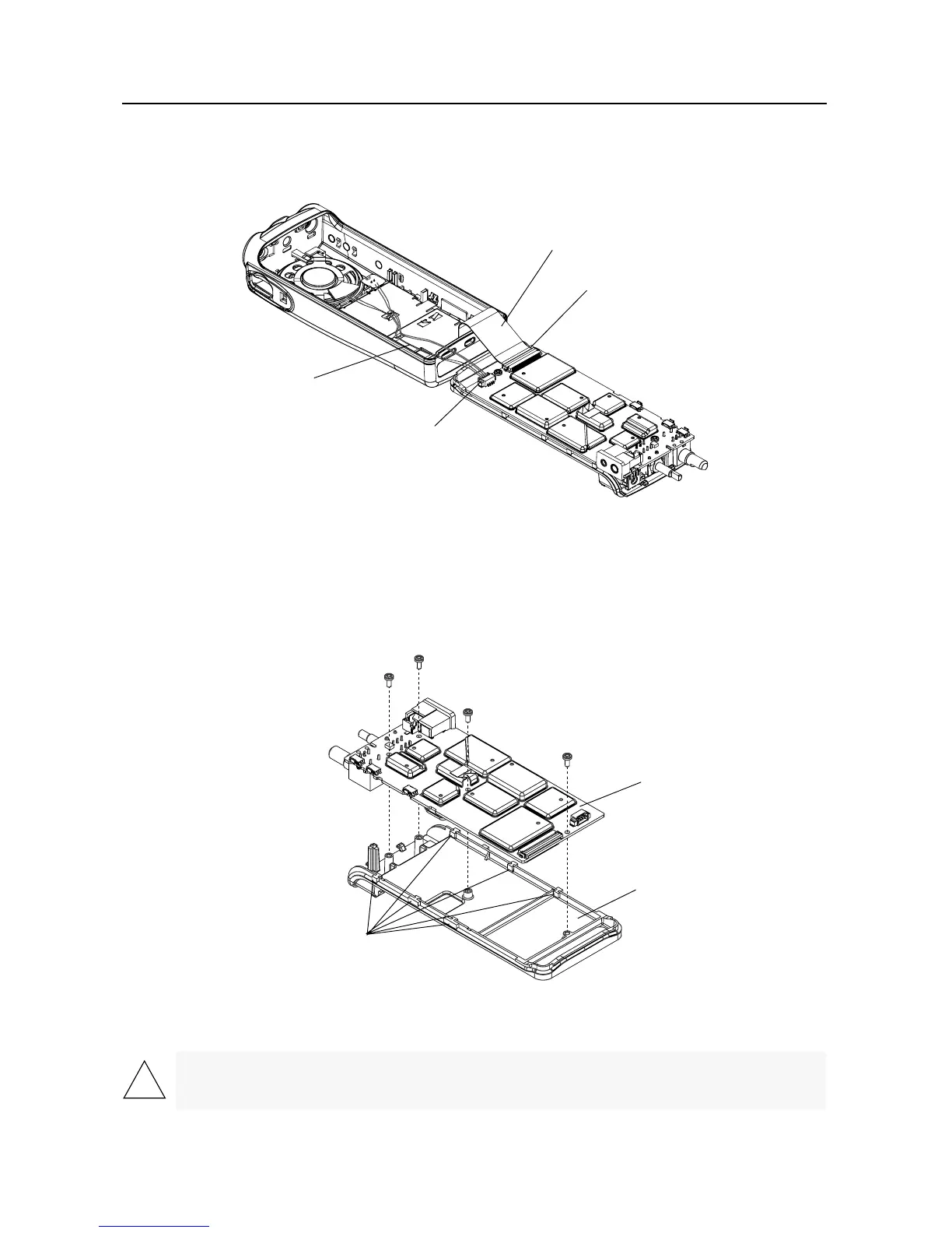
6. Lay the chassis down. Rotate the front cover backward and slightly away from the chassis.
7. Lift the latch on the main circuit board to release the jumper ßex from its connector.
8. Unplug the wires from the 4-pin connector.
5.2 Chassis Assembly Disassembly
Use a TORXª screwdriver with a T6 head to remove the four screws holding the main board to the
chassis.
1. Lift the main board from the chassis (See Figure 3-5).
Figure 3-4 Unlatch Flex Connectors
Figure 3-5 Remove Main Board from Chassis
CAUTION: Refer to the CMOS CAUTION paragraph on Page 3-2 before removing the main board. Be
sure to use ESD protection when handling circuit boards.
Latch
Jumper Flex
4-Pin Connector
Wire Assembly
Main Board
Radio Chassis
O-Ring
Retaining Features

 Loading...