10
4.3. Boundary wire
You may choose to either install the boundary wire above or below the soil of the lawn. A mixture of installations is
acceptable as well. It is recommended to cut the lawn as low as possible where the wire will be installed beforehand.
- Installation on the soil
Attach the boundary wire onto your lawn with pegs. This makes adjusting the boundary wire possible during the first
few weeks of operation. Place the boundary wire firmly onto the ground, fastening it to the ground with the provided
pegs. Make sure that the Robotic Mower cannot cut the wire at any point. The wire will not be visible after a few
weeks. Place the pegs at intervals of 1 m between each other.
- Installation in the soil
Cut a groove in the ground with an edge cutter or straight spade. Place the boundary wire in to a maximum depth of
5 cm, if you wish to install the wire below the lawn soil. This allows you to scarify or aerate the lawn in the future
without damaging the boundary wire.
- Important!
Hard or dry ground may cause pegs to break when driving them in. Water the lawn if it is very dry prior to the wire
installation.
NOTICE: Damage to the boundary wire are not covered by warranty.
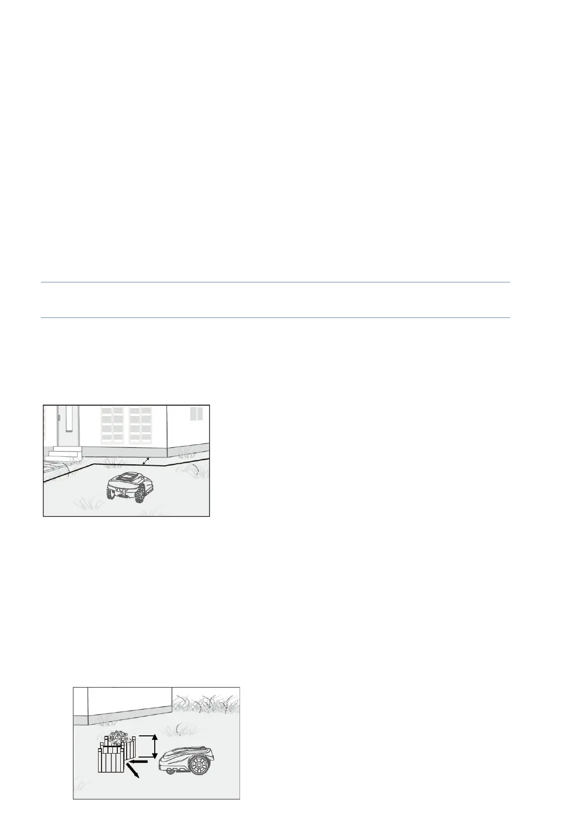
- Important! The boundary wire should be installed 30cm from the edge of the perimeter
When the Robotic Mower approaches any boundary wire, the sensors which are installed in the front part of the
mower will detect it, but before turning around, the Robotic Mower will overrun the boundary by approximately 20 to
30 cm, so please use this information when you create the layout of your boundary. The wire should be 30cm from
the edge or obstacle. (Fig.6).
Fig.6
- Repairs / Joining the boundary wire
For repairs and joining boundary wires the 3M™ Scotchlok™ Electrical IDC 314 connectors are recommended.
These are corrosion resistant and do not require the wires to be stripped.
Insert both wire ends in the connector.
Check that the wires are fully inserted into the connector so that the ends are visible through the transparent area
on the other side of the connector. Now press down the button on top of the connector fully. Use polygrip pliers to
completely press down the button on the connector.
- Obstacles higher than 100 mm
Fixed obstacles higher than 100 mm, such as trees, walls, fences, garden
f
urni
t
ur
e,
etc, are recognized by the
impact sensors. The Robotic Mower will stop, drive backwards and then turn around to cut in another
direction
(Fig.7).
Soft, unstable and fragile
obstacles must be protected by creating a boundary island around
them.
Fig.7