Trigger Box Quick Start Guide
8
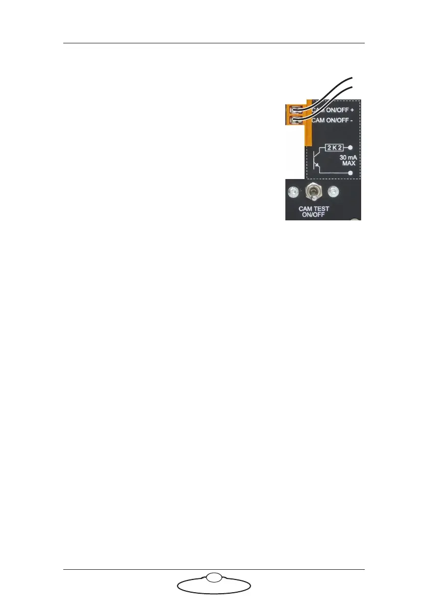
Using the Camera On/Off trigger output
The CAM ON/OFF trigger output on the Trigger
Box consists of a pair of connectors with an internal
relay. When the External Camera (Ext. Cam)
trigger is activated from Flair software, the relay for
this pair closes, completing the external circuit and
triggering the camera.
The camera that is being triggered must provide its
own power for the trigger circuit, up to 250 Volts
AC or 30 volts DC, 30 milliamps maximum current.
The internal resistance for this circuit is 2.2
kilo-ohms.
In order for the Camera On/Off Trigger output to
reach the camera via the Trigger Box’s CAM ON/OFF connectors, two
other conditions must be met:
• The Trigger Box must be plugged into the SYNC connector on
the ribbon cable. The Camera Trigger Output wires do not
reach the BLOOP or TRIGGER ribbon cable connectors — see
Connecting the cables on page 2.
• The CAM TEST ON/OFF switch must be Off. This routes the
Camera Trigger output to the connectors instead of to the
Trigger Box’s internal simulated camera (Sync generator).
You can test the Camera On/Off trigger output at the same time that you
test the Sync signal. See Testing the Sync input and Camera On/Off trigger
output on page 12.