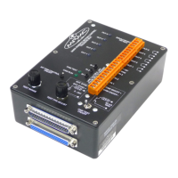
Trigger Box Quick Start Guide
12
Testing the Sync input and Camera On/Off trigger output
The Trigger Box has a built-in simulated camera (Sync signal generator)
which you can use to test that the Flair software can correctly receive a
synchronisation (Sync) signal, via the RT-14 unit, without needing to
attach a real camera to the system.
You can turn the Sync signal generator on or off from either the Trigger
Box or from Flair. If you do it from Flair, this also tests the External
Camera On/Off trigger facility in Flair, as this is what you use to trigger
the simulated camera (Sync generator) in the Trigger Box.
To test the Sync input, the Trigger Box can be plugged into any connector
on the ribbon cable. To test Sync input and Camera On/Off trigger
together, the Trigger Box must be plugged into the SYNC connector on
the ribbon cable.
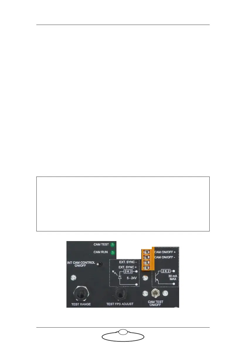
Sync and camera controls
The next diagram shows the controls for generating a simulated Sync
signal and sending it to Flair, and using the External Camera trigger in
Flair to activate that signal.
Hint
In the connector labels on the Trigger Box, the word “CAM” refers to
the real camera whose trigger wires you attach to the Trigger Box. In
the switch and LED labels on the Trigger Box, the word “CAM”
refers to the internal simulated “camera” in the Trigger Box that is
generating the test Sync signal.