Trigger Box Quick Start Guide
5
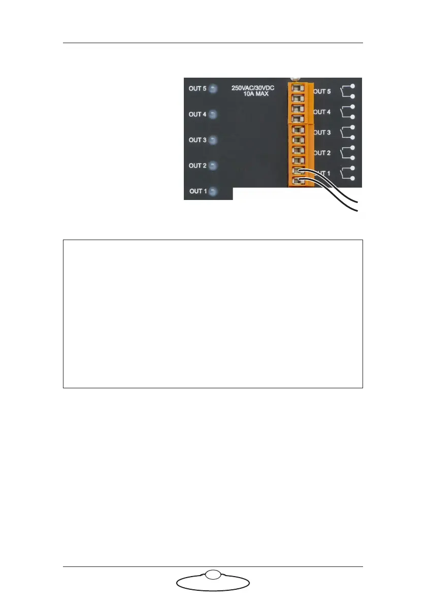
Using the trigger outputs
Each trigger output
consists of a pair of
connectors, a
corresponding LED on the
panel, and an internal relay.
When a trigger is activated
from Flair software, the
relay for that pair closes,
completing the external
circuit and triggering the
external device. The
corresponding LED (also
numbered OUT 1 to OUT 5) is lit during activation.
The external device that is being triggered must provide its own power for
the trigger circuit, up to 250 Volts AC or 30 volts DC, 10 Amp maximum
resistive current or 3 Amp maximum inductive current. Contact MRMC
for further advice on maximum current for triggering external devices.
In Flair, the button for trigger OUT 1 is labelled Bloop by default unless
you have changed it, as it is usually used to trigger the Bloop light. The
other buttons in Flair use label numbers that match the trigger outputs on
the Trigger Box; that is, Flair button Trigger 2 corresponds to OUT 2,
button Trigger 3 corresponds to OUT 3, etc. Again, you can change these
names in Flair by using the same menu options that you use to add
triggers to a move: Setups > Outputs > #1 - Bloop, #2, #3, etc. See the
Flair documentation for details.
Hint
The LED is powered by the circuit that closes the relay — not by the
external circuit that is completed when the relay closes. Therefore a
lit LED only indicates that Flair has activated the trigger; it is not a
check to see if the external circuit now has current flowing through
it.
Trigger Output 1 (Bloop) is a special case due to the way the ribbon
cable is cut (see page 2). The Trigger 1 Output signal will only reach
the Trigger Box if the Trigger Box is plugged into the SYNC or
BLOOP connectors.