3.2.1 Electrical Connection - PrimaX P
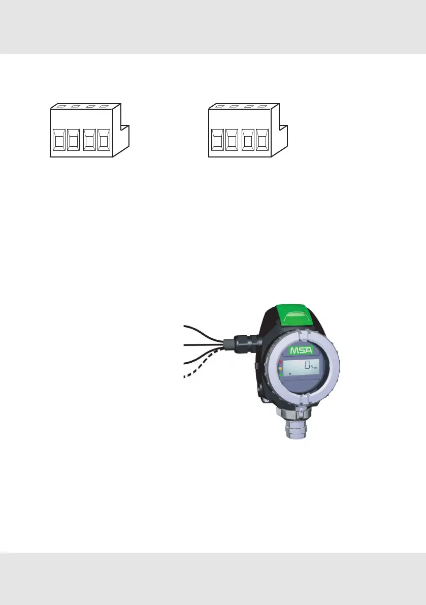
Terminal PrimaX P
Figure 3 Terminal PrimaX P
(3-wire sensor)
Figure 4 Terminal PrimaX P
(4-wire sensor)
1 Power supply (+), 24V DC 1 Power supply (+), 24V DC
2 0 V DC 2 0 V DC
3 4–20mA (Signal) 3 4–20mA (Signal)
4 empty 4 Isolated ground
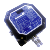
PrimaX P
Power supply (+) 24V DC
0V DC (-)
4–20mA(Signal)
Isolated ground
Figure 5 3-wire/4-wire connection - PrimaX P
1. Unscrew the interlock between cover and bayonet joint of sensor.
2. Unscrew the aluminum lid of the enclosure.
3. Unplug the 4-way terminal block.
The block is located behind a plastic cover above the display.
15 PrimaX GB
3 Installation