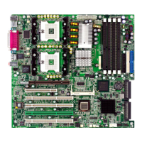
This document describes the E7505 Master-LS2 (MS-9121 v1.X) E-ATX Mainboard, a high-end solution for professional workstation and server markets.
Copyright Notice
The material in this document is the intellectual property of MICRO-STAR INTERNATIONAL. While care is taken in preparation, no guarantee is given as to the correctness of its contents. Products are under continual improvement, and the right to make changes without notice is reserved.
Trademarks
All trademarks are the properties of their respective owners. Intel® and Pentium® are registered trademarks of Intel Corporation. PS/2 and OS®/2 are registered trademarks of International Business Machines Corporation. Windows® 95/98/2000/NT/XP are registered trademarks of Microsoft Corporation. Netware® is a registered trademark of Novell, Inc. Award® is a registered trademark of Phoenix Technologies Ltd. AMI® is a registered trademark of American Megatrends Inc.
Revision History
- Revision V1.0: First release, October 2002.
Technical Support
For system problems not resolved by the user's manual, contact your place of purchase or local distributor. Alternatively, visit the MSI website for FAQ, technical guides, BIOS updates, driver updates, and other information at http://www.msi.com.tw/. Technical staff can be contacted at support@msi.com.tw.
Safety Instructions
- Always read safety instructions carefully.
- Keep this User's Manual for future reference.
- Keep this equipment away from humidity.
- Lay this equipment on a reliable flat surface before setting it up.
- The enclosure openings are for air convection to prevent overheating; DO NOT COVER THE OPENINGS.
- Ensure the power source voltage is correctly adjusted (110/220V) before connecting to the power inlet.
- Place the power cord so it cannot be stepped on or have anything placed over it.
- Always unplug the power cord before inserting any add-on card or module.
- All cautions and warnings on the equipment should be noted.
- Never pour liquid into openings, as it could cause damage or electrical shock.
- If any of the following occurs, have the equipment checked by service personnel:
- The power cord or plug is damaged.
- Liquid has penetrated the equipment.
- The equipment has been exposed to moisture.
- The equipment does not work well or as per the User's Manual.
- The equipment has been dropped and damaged.
- The equipment shows obvious signs of breakage.
- DO NOT LEAVE THIS EQUIPMENT IN AN UNCONDITIONED STORAGE TEMPERATURE ABOVE 60°C (140°F), as it may damage the equipment.
CAUTION: Danger of explosion if the battery is incorrectly replaced. Replace only with the same or equivalent type recommended by the manufacturer.
Mainboard Specifications
CPU
- Supports single/dual Intel® Xeon™ processors with 512K L2 cache.
- Supports 1.8GHz – 2.8GHz and up.
Chipset
- Intel® E7505 North Bridge:
- Supports 100MHz/133MHz system clock.
- Intel® NetBurst micro-architecture supports 400MHz/533MHz system bus.
- System bus bandwidth of 3.2GB/s & 4.27GB/s.
- Supports DDR200/266 memory.
- Supports AGP 8x/4x.
- Intel® ICH4 South Bridge:
- Hi-Speed USB (USB2.0) controller, 480Mb/sec.
- 2-channel Ultra ATA 100 bus Master IDE controller.
- PCI Master 2.2.
- I/O, APIC.
- AC'97 2.2 interface.
- 3 UHCI Host controllers and 1 EHCI Host controller.
- Intel® P64H2 chipset:
- Supports 64-bit PCI-X slots at 100MHz.
- Connects directly to the MCH and provides a dedicated path for high performance I/O.
Main Memory
- Supports eight memory banks using four 184-pin DDR DIMMs.
- Supports up to 8GB PC2100/PC1600 DDR SDRAMs.
- Supports 2.5V DDR SDRAM.
Slots
- 1 x 8X AGP Pro (50 Watts) slot.
- 3 x 64bit/100MHz PCI-X slot with support for Zero Channel RAID (PCIX3).
- 1 x 64bit/100MHz PCI-X slots.
- 1 x 32bit/33MHz PCI slot.
- 1 x mini PCI slot.
- PCI2.2, PCI-X, and AGP 3.0 compliant.
Onboard IDE
- An IDE controller on the ICH4 chipset provides IDE HDD/CD-ROM with PIO, Bus Master and Ultra DMA100/66/33 operation modes.
- Can connect up to four IDE devices.
On-Board Peripherals
- 1 x floppy port supports 2 FDDs with 360K, 720K, 1.2M, 1.44M and 2.88Mbytes.
- 2 x serial ports (COM A + COM B).
- 1 x parallel port supports SPP/EPP/ECP mode.
- 1 x RJ-45 LAN port.
- 2 x SCSI connectors.
- 2 x IEEE 1394 ports (Rear x 1/Front x 1) provided by add-in card (Optional).
- 4 x USB 2.0 ports (Rear x 2/Front x 2).
Onboard SCSI
- Integrated LSI 53C1030 Ultra320 SCSI controller.
- Supports dual channels.
Onboard LAN
- Integrated Broadcom® BCM5703CKHB Gigabit Ethernet controller.
- 64bit/100MHz PCI-X bus interface.
Onboard Audio
- AC'97 audio codec integrated in ICH4 south bridge.
- AD 1885 software audio codec.
- Vertical audio phonejacks (MIC, Line-In, Line-Out) onboard.
Video Add-In Card (Optional)
- ATI Rage™ XL video controller with 8MB memory.
- Mini PCI interface.
IEEE 1394 Add-In Card (Optional)
- TI TSB43AB22 1394a Link Layer Controller.
- Mini PCI interface.
BIOS
- The mainboard BIOS provides "Plug & Play" BIOS which detects peripheral devices and expansion cards automatically.
- The mainboard provides a Desktop Management Interface (DMI) function which records mainboard specifications.
Dimension
- Extended ATX Form Factor: 12" x 13".
- Compliant with SSI EEB 3.0.
Mounting
MSI Special Features
PC Alert™ III
This utility, found on the CD-ROM, acts as a PC doctor to detect real-time hardware status:
- Monitors CPU & system temperatures.
- Monitors fan speed(s).
- Monitors system voltage.
- Monitors chassis intrusion.
If any item is abnormal, the main screen will display it highlighted in red until the user disables the warning.
Live BIOSTM/Live Driver™
This tool detects and updates BIOS/drivers online, eliminating the need to search for correct versions. Install "MSI Live Update 2" and double-click its icon. The application allows you to:
- Live BIOS: Updates the BIOS online.
- Live Driver: Updates the drivers online.
- Live VGA BIOS: Updates the VGA BIOS online.
- Live VGA Driver: Updates the VGA driver online.
- Live Utility: Updates the utilities online.
If a function is not supported, a "sorry" message is displayed. Refer to the companion CD's "Live Update Guide" for more information.
Live Monitor™
This tool schedules searches for the latest BIOS/driver versions on the MSI Web site. Install "MSI Live Update 2" and double-click the "MSI Live Monitor" icon in the taskbar. The dialog box allows specifying search frequency and changing LAN settings. Right-clicking the icon provides options:
- Auto Search: Searches for BIOS/driver versions immediately.
- View Last Result: Views the last search result.
- Preference: Configures search functions and schedules.
- Exit: Exits the application.
- FAQ: Provides a link to a database of common questions about MSI products.
Hardware Setup
Central Processing Unit: CPU
The mainboard supports Single/Dual Intel® Xeon™ processors using two Socket 604 CPU sockets.
- Single CPU Installation: Always install the CPU on the CPU1 socket.
- Dual CPU Installation: Use the same type of CPUs running at the same FSB frequency.
Important: Always attach a Heat Sink and cooling fan to the CPU to prevent overheating. If not included, purchase and install them before powering on.
CPU Installation Procedures
- Turn off power and unplug the power cord.
- Pull the lever sideways and raise it to a 90-degree angle.
- Look for the gold arrow on the CPU and align it with the gold arrow on the socket. The CPU only fits in the correct orientation.
- If the CPU is correctly installed, pins should be completely embedded and not visible. Incorrect installation may damage the mainboard.
- Press the CPU down firmly into the socket and close the lever. If the CPU is not fully seated, the lever will not close. Ensure the CPU is properly and completely embedded.
CPU Core Speed Derivation Procedure
- If CPU Clock = 100MHz and Core/Bus ratio = 14, then CPU core speed = Host Clock x Core/Bus ratio = 100MHz x 14 = 1.4 GHz.
Overheating: Overheating seriously damages the CPU and system. Ensure the cooling fan works properly.
Replacing the CPU: Always turn off the ATX power supply or unplug the power cord from a grounded outlet first.
Memory
The mainboard provides 4 slots for 184-pin DDR DIMM modules, supporting up to 8 GB. Install PC2100/DDR266 or PC1600/DDR200 DDR SDRAM modules.
Memory Speed/CPU FSB Support Matrix:
- 400MHz FSB: DDR200 (Yes), DDR266 (Yes)
- 533MHz FSB: DDR200 (No), DDR266 (Yes)
DIMM Module Combination:
Install at least two DIMM modules. Each slot supports up to 2GB. Install single- or double-sided modules as needed, but memory modules must be installed IN PAIRS.
Memory modules can be installed in any combination as follows:
- DIMM1 (128MB-2GB), DIMM2 (128MB-2GB): System Density 256MB-4GB
- DIMM1 (128MB-2GB), DIMM2 (128MB-2GB), DIMM3 (128MB-2GB), DIMM4 (128MB-2GB): System Density 512MB-8GB
Important: Install memory modules of the same type and density on DDR DIMMs "in pairs" -- {DIMM1 & DIMM2} {DIMM3 & DIMM4}.
Installing DDR Modules
- The DDR DIMM has one notch in the center; it will only fit in the right orientation.
- Insert the DIMM module vertically into the slot. Push until the golden finger is deeply inserted.
Important: The golden finger should be barely visible if the module is properly inserted.
- The plastic clip at each side of the DIMM slot will automatically close.
Power Supply
The mainboard supports SSI power supply. Ensure all components are installed before inserting the power supply connector.
SSI 24-Pin Power Connector: POWER1
Connect the SSI power supply plug, ensuring proper orientation and pin alignment. Push firmly into the connector.
POWER1 Pin Definition:
- PIN 1-3: +3.3V, GND
- PIN 4-6: +5V, GND, +5V
- PIN 7-9: GND, PWR OK, 5VSB
- PIN 10-12: +12V, +12V, +3.3V
- PIN 13-15: +3.3V, -12V, GND
- PIN 16-18: PS-ON#, GND, GND
- PIN 19-21: GND, 3VSB, +5V
- PIN 22-24: +5V, +5V, GND
SSI 8-Pin Power Connector: POWER2
This connector provides 12V power output to the CPU.
POWER2 Pin Definition:
- PIN 1-4: GND, GND, GND, GND
- PIN 5-8: +12V, +12V, +12V, +12V
Back Panel
The back panel provides the following connectors:
- Mouse
- Keyboard
- USB ports
- Parallel Port
- COM A
- COM B
- LAN
- MIC
- L-In
- L-Out
Mouse Connector
A standard PS/2® mouse mini DIN connector is provided for attaching a PS/2® mouse.
Pin Definition (PS/2 Mouse, 6-pin Female):
- PIN 1: Mouse DATA
- PIN 2: NC (No connection)
- PIN 3: GND (Ground)
- PIN 4: VCC (+5V)
- PIN 5: Mouse Clock
- PIN 6: NC (No connection)
Keyboard Connector
A standard PS/2® keyboard mini DIN connector is provided for attaching a PS/2® keyboard.
Pin Definition (PS/2 Keyboard, 6-pin Female):
- PIN 1: Keyboard DATA
- PIN 2: NC (No connection)
- PIN 3: GND (Ground)
- PIN 4: VCC (+5V)
- PIN 5: Keyboard Clock
- PIN 6: NC (No connection)
USB Connectors
The mainboard provides a UHCI (Universal Host Controller Interface) Universal Serial Bus root for attaching USB devices.
USB Port Description (8-pin):
- PIN 1: VCC (+5V)
- PIN 2: -Data 0 (Negative Data Channel 0)
- PIN 3: +Data0 (Positive Data Channel 0)
- PIN 4: GND (Ground)
- PIN 5: VCC (+5V)
- PIN 6: -Data 1 (Negative Data Channel 1)
- PIN 7: +Data 1 (Positive Data Channel 1)
- PIN 8: GND (Ground)
Serial Port Connector: COM A & COM B
Two 9-pin male DIN connectors are provided for serial ports COM A and COM B. These are 16550A high-speed communication ports that send/receive 16 bytes FIFOs.
Pin Definition (9-Pin Male DIN Connectors):
- PIN 1: DCD (Data Carry Detect)
- PIN 2: SIN (Serial In or Receive Data)
- PIN 3: SOUT (Serial Out or Transmit Data)
- PIN 4: DTR (Data Terminal Ready)
- PIN 5: GND (Ground)
- PIN 6: DSR (Data Set Ready)
- PIN 7: RTS (Request To Send)
- PIN 8: CTS (Clear To Send)
- PIN 9: RI (Ring Indicate)
Audio Port Connectors
- Line Out: For Speakers or Headphones.
- Line In: For external CD player, Tape player, or other audio devices.
- Mic: For microphones.
1/8" Stereo Audio Connectors: MIC, Line In, Line Out.
Parallel Port Connector: LPT1
A 25-pin female centronic connector is provided as LPT. It supports Enhanced Parallel Port (EPP) and Extended Capabilities Parallel Port (ECP) mode.
Pin Definition (25-pin):
- PIN 1: STROBE
- PIN 2-9: DATA0-DATA7
- PIN 10: ACK#
- PIN 11: BUSY
- PIN 12: PE (Paper End)
- PIN 13: SELECT
- PIN 14: AUTO FEED#
- PIN 15: ERR#
- PIN 16: INIT#
- PIN 17: SLIN#
- PIN 18-25: GND (Ground)
RJ-45 LAN Jack: Giga-bit LAN
The mainboard provides one standard RJ-45 jack for connection to a Local Area Network (LAN). Giga-bit LAN enables data transfer at 1000, 100, or 10Mbps. Pin assignments vary depending on the transfer rate. Note that Pin 1/2, 3/6, 4/5, 7/8 must work in pairs.
10/100 LAN Pin Definition:
- PIN 1: TDP (Transmit Differential Pair)
- PIN 2: TDN (Transmit Differential Pair)
- PIN 3: RDP (Receive Differential Pair)
- PIN 4: NC (Not Used)
- PIN 5: NC (Not Used)
- PIN 6: RDN (Receive Differential Pair)
- PIN 7: NC (Not Used)
- PIN 8: NC (Not Used)
Giga-bit LAN Pin Definition:
- PIN 1: TDP (Differential Pair 0+)
- PIN 2: TDN (Differential Pair 0-)
- PIN 3: RDP (Differential Pair 1+)
- PIN 4: D2P (Differential Pair 2+)
- PIN 5: D2N (Differential Pair 2-)
- PIN 6: RDN (Differential Pair 1-)
- PIN 7: D3P (Differential Pair 3+)
- PIN 8: D3N (Differential Pair 3-)
Connectors
The mainboard provides connectors for FDD, IDE HDD, case, modem, LAN, USB Ports, IR module, and CPU/System/Power Supply FAN.
Floppy Disk Drive Connector: FDD1
Supports 360K, 720K, 1.2M, 1.44M, and 2.88M floppy disk types.
Chassis Intrusion Switch Connector: JCI1
This 2-pin connector connects to a chassis switch. If the chassis is opened, the switch shorts, the system records this status, and a warning message appears. To clear the warning, enter the BIOS utility and clear the record.
Hard Disk Connectors: IDE1/2
The mainboard has a 32-bit Enhanced PCI IDE and Ultra DMA 33/66/100 controller, providing PIO mode 0~4, Bus Master, and Ultra DMA 33/66/100 functions. Connect up to four hard disk drives, CD-ROM, 120MB Floppy (reserved for future BIOS), and other devices.
- IDE1 (Primary IDE Connector): The first hard drive should always be connected here. It can connect a Master and a Slave drive. Configure the second hard drive to Slave mode by setting its jumper.
- IDE2 (Secondary IDE Connector): Can also connect a Master and a Slave drive.
Important: If installing two hard disks on a cable, configure the second drive to Slave mode via its jumper. Refer to hard disk documentation for jumper settings.
Fan Power Connectors: CPUFAN1/2, SYSFAN1/2/3/4/5
These connectors support system cooling fans with +12V and three-pin head connectors.
- Wiring: Red wire is positive (+12V), black wire is Ground (GND).
- CPU Fan Control: If the mainboard has a System Hardware Monitor chipset, use a specially designed fan with a speed sensor to utilize CPU fan control.
Important: Always consult vendors for proper CPU cooling fans.
Front Panel Connectors: JFP2, JFP3
Two front panel connectors for electrical connection to front panel switches and LEDs. JFP2 is compliant with Intel® Front Panel I/O Connectivity Design Guide.
JFP3 Pin Definition:
- PIN 1: GND
- PIN 2: SPK-
- PIN 3: SLED
- PIN 4: BUZ+
- PIN 5: PLED
- PIN 6: BUZ-
- PIN 7: NC
- PIN 8: SPK+
JFP2 Pin Definition:
- PIN 1: HD_LED_P (Hard disk LED pull-up)
- PIN 2: FP PWR/SLP (MSG LED pull-up)
- PIN 3: HD_LED_N (Hard disk active LED)
- PIN 4: FP PWR/SLP (MSG LED pull-up)
- PIN 5: RST_SW_N (Reset Switch low reference pull-down to GND)
- PIN 6: PWR_SW_P (Power Switch high reference pull-up)
- PIN 7: RST_SW_P (Reset Switch high reference pull-up)
- PIN 8: PWR_SW_N (Power Switch low reference pull-down to GND)
- PIN 9: RSVD_DNU (Reserved. Do not use.)
SCSI LED Connector: J18
Connect J18 to the LED connector on an add-on SCSI adaptor. The HDD LED will blink when the add-on SCSI device is active.
Pin Definition (J18):
- PIN 1: VCC5
- PIN 2: SCSI LED
- PIN 3: HDD LED
- PIN 4: VCC5
Front USB Connector: JUSB3
Provides one front Universal Serial Bus connector for optional USB ports.
Pin Definition (JUSB3):
- PIN 1: +5V
- PIN 2: +5V
- PIN 3: USBP2-
- PIN 4: USBP3-
- PIN 5: USBP2+
- PIN 6: USBP3+
- PIN 7: GND
- PIN 8: GND
- PIN 9: NC
- PIN 10: Key Removed
CD-In Connector: JCD1
The connector for CD-ROM audio.
Wake On LAN Connector: JWL1
Allows connecting to a LAN card with Wake On LAN function. This enables remote computer wake-up via a local area network.
Pin Definition (JWL1):
- PIN 1: GND
- PIN 2: NC
- PIN 3: SV5B
- PIN 4: MP_WAKEUP
Important: To use this function, a power supply that provides enough power for this feature (750 mA 5V Stand-by) is needed.
Ultra320 SCSI Connectors: SCSI 1/2
SCSI (Small Computer System Interface) is a hardware interface for connecting up to 15 peripheral devices. The mainboard provides onboard dual SCSI channels (SCSI 1 & SCSI 2) for connecting SCSI devices such as SCSI hard disks.
Jumpers
The motherboard provides jumpers to set computer functions.
Clear CMOS Jumper: JBAT1
The CMOS RAM retains system configuration data via an external battery. To clear system configuration data, use JBAT1.
- Turn off the system.
- Short pins 2-3 to clear data.
- Return to pins 1-2 position.
Important: Avoid clearing CMOS while the system is on; it will damage the mainboard.
Determines the system's mode upon power-on.
- Normal Mode (1-2 shorted): System enters the assigned OS.
- Configure Mode (2-3 shorted): System directly enters BIOS setup utility for configuration.
- Recovery Mode (no pins shorted): Insert a boot disk into the floppy drive before powering on. The system reads the boot disk and enters DOS, allowing BIOS update with a Flash utility.
BIOS Flash Jumper: J14
Protects the BIOS boot block from virus infection.
- BIOS flash locked (1-2 shorted): BIOS boot block cannot be accessed, preventing BIOS update.
- BIOS flash unlocked (2-3 shorted): Disables BIOS flash protection for updates.
Buzzer Enable/Disable Jumper: J16
Enables/disables the onboard buzzer.
- Disable Buzzer (1-2 shorted)
- Enable Buzzer (2-3 shorted)
ASR Enable/Disable Jumper: J17
Enables/disables the ASR (Auto Server Reboot) function.
- Disable ASR (1-2 shorted)
- Enable ASR (2-3 shorted)
Slots
The motherboard provides one AGP Pro slot, one 32-bit Master PCI slot, one Mini PCI slot, and four 64-bit PCI-X slots.
AGP (Accelerated Graphics Port) Pro Slot
Allows insertion of AGP/AGP Pro graphics cards. AGP is a 66MHz, 32-bit channel for 3D graphics, allowing direct access to main memory.
PCI (Peripheral Component Interconnect) Slots
PCI slots allow insertion of expansion cards. Unplug the power supply before adding/removing cards. Read card documentation for hardware/software settings.
- 32-bit PCI bus: 32 data lines, 33MHz.
- 64-bit PCI-X bus: 64 data lines, 100MHz. Increases throughput and system performance. The 64-bit PCI-X Slot 3 (green) is the only slot for Zero Channel RAID (ZCR) card installation.
Mini PCI bus
Used to connect MS-9513 VGA card or MS-9514 IEEE 1394 card.
Installing the card:
- Locate the Mini PCI slot.
- Place the card over the slot and gently insert both ends slantways (45 degrees) until the golden finger is fully inserted.
Important: The golden finger should be barely visible if the module is properly inserted.
- Align the card's fixing holes with the supporters on the mainboard and press down until locked.
- Push the retaining clips (on both ends of the slot) inwards until they lock onto the notches. The card should be secure.
Removing the card:
- Gently push the retaining clips outwards. Hold the card lightly. Use long nose pliers to clip one supporter and press it downwards until it withdraws from the fixing hole.
- Clip the other supporter and press it downwards until it withdraws.
- The card will automatically bound upwards.
- Remove the card from the Mini PCI slot.
Interrupt Request Routing
IRQs (interrupt request lines) are hardware lines for devices to send interrupt signals to the microprocessor.
DEVICE | INT A# | INT B# | INT C# | INT D#
- AGP | PIRQA_L | PIRQB_L | N/A | N/A
- PCI Slot 1 | PIRQF_L | PIRQG_L | PIRQH_L | PIRQE_L
- PCI Slot 2 (Mini PCI) | PIRQG_L | N/A | N/A | N/A
- P64H2 | PIRQC_L | N/A | N/A | N/A
- LSI53C1030 | PAIRQ8 | PAIRQ9 | N/A | N/A
- PCI-X Slot 3 (SCSI RAID) | PAIRQ0 | PAIRQ1 | N/A | N/A
- PCI-X Slot 4 | PAIRQ4 | PAIRQ5 | PAIRQ6 | PAIRQ7
- GIGABIT LAN | PBIRQ0 | N/A | N/A | N/A
- PCI-X Slot 1 | PBIRQ4 | PBIRQ5 | PBIRQ6 | PBIRQ7
- PCI-X Slot 2 | PBIRQ8 | PBIRQ9 | PBIRQ10 | PBIRQ11
- MS-9513 (VGA Card) | PIRQG_L | N/A | N/A | N/A
- MS-9514 (1394 Card) | PIRQG_L | N/A | N/A | N/A
BIOS Setup
Entering Setup
Upon power-on, the system performs POST. When "Press DEL to enter SETUP" appears, press to enter Setup. If the message disappears, restart the system by turning it off/on or pressing RESET, or simultaneously pressing , , and .
Control Keys
- <↑>, <↓>: Move to previous/next item.
- <←>, <→>: Move to item left/right.
- : Select item.
- : Jumps to Exit menu or returns to main menu from submenu.
- <+/PU>, <-/PD>: Increase/decrease numeric value or make changes.
- : General help (Status Page Setup Menu and Option Page Setup Menu only).
- : Restore previous CMOS value (Option Page Setup Menu only).
- : Load default CMOS value from Fail-Safe default table (Option Page Setup Menu only).
- : Load Optimized defaults.
- : Save all CMOS changes and exit.
Getting Help
The first menu upon entering Setup is the Main Menu.
Main Menu: Lists setup functions. Use arrow keys (↑↓) to select items. Description of highlighted function is at the bottom.
Sub-Menu: A right pointer symbol indicates a submenu. Use arrow keys (↑↓) to highlight and to open. Use control keys to enter values and move fields. Press to return to the main menu.
General Help : Provides a General Help screen from any menu. Lists appropriate keys and selections. Press to exit.
Important: BIOS descriptions are subject to continuous updates for performance and may differ slightly from the latest BIOS.
The Main Menu
The Award Workstation BIOS CMOS Setup Utility Main Menu has twelve configurable functions and two exit choices. Use arrow keys to navigate and to select.
- Standard CMOS Features: Basic system configurations (time, date, etc.).
- Advanced BIOS Features: Special enhanced features.
- Advanced Chipset Features: Change chipset register values to optimize performance.
- Integrated Peripherals: Settings for integrated peripherals.
- Power Management Setup: Settings for power management.
- PNP/PCI Configurations: PnP/PCI system settings (appears if supported).
- PC Health Status: Displays PC health status.
- Frequency/Voltage Control: Settings for frequency/voltage control.
- Load Fail-Safe Defaults: Loads BIOS default values for minimal but stable performance.
- Load Optimized Defaults: Loads BIOS default values for optimal system operations.
- Set Supervisor/User Password: Sets user and supervisor passwords.
- Save & Exit Setup: Saves changes and exits.
- Exit Without Saving: Abandons changes and exits.
Standard CMOS Features
This menu has 10 categories. Use arrow keys to highlight and / to switch values.
- Date (mm:dd:yy): Sets system date. Format: .
- day: Read-only (Sun-Sat).
- month: Jan-Dec.
- date: 1-31 (numeric keys).
- year: Adjustable.
- Time (hh:mm:ss): Sets system time. Format: .
- IDE Primary/Secondary Master/Slave: Select Manual, None, Auto. Drive specifications must match the drive table. If Manual, enter information from hard disk vendor documentation. If SCSI or CD-ROM, select "None".
Drive A/B
Sets floppy drive type. Options: None, 360K, 5.25 in., 1.2M, 5.25 in., 720K, 3.5 in., 1.44M, 3.5 in., 2.88M, 3.5 in.
Video
Controls primary monitor video adapter type. Options: EGA/VGA, CGA 40, CGA 80, Mono.
Halt On
Determines if the system stops on boot error.
- All Errors: Stops on any error.
- No Errors: Does not stop on any error.
- All, But Keyboard: Does not stop on keyboard error.
- All, But Diskette: Does not stop on disk error.
- All, But Disk/Key: Does not stop on disk or keyboard error.
Advanced BIOS Features
Virus Warning
Sets IDE Hard Disk boot sector protection. Enabled: BIOS displays a warning and beeps if data is written to this area. Options: Disabled, Enabled.
CPU L1 & L2 Cache
Enables/disables internal (L1) and external (L2) cache. Options: Disabled, Enabled.
CPU L3 Cache
Enables/disables L3 cache. Options: Enabled, Disabled.
CPU Hyper-Threading
Enabled: Improves performance of multi-threaded code on Hyper-Threading-enabled Intel® Pentium® 4 or Xeon™ processors with HT Technology, Intel® Chipsets supporting HT Technology, and a BIOS/OS that supports HT Technology. Options: Enabled, Disabled.
First/Second/Third Boot Device
Sets the boot device sequence.
- Floppy: Boots from floppy drive.
- LS120: Boots from LS-120 drive.
- HDD-0: Boots from first HDD.
- SCSI: Boots from SCSI device.
- CDROM: Boots from CD-ROM.
- HDD-1/2/3: Boots from second/third/fourth HDD.
- ZIP100: Boots from ATAPI ZIP drive.
- LAN: Boots from network drive.
- Disabled: Disables this sequence.
Important: Available settings vary based on installed bootable devices.
Boot Other Device
Enabled: System attempts to boot from other devices if 1st/2nd/3rd boot devices fail.
Swap Floppy Drive
Enabled: Swaps floppy drives A: and B:.
Boot Up Floppy Seek
Enabled: BIOS searches for floppy drives at boot time (drive activity light comes on, head moves). Options: Disabled, Enabled.
Floppy Disk Access Control
Controls write protection for floppy drives. Options: R/W, Read Only.
Boot Up NumLock Status
Sets Num Lock status on power-on. On: Num Lock key is on. Off: Arrow keys on numeric keypad are used. Options: On, Off.
Gate A20 Option
Sets Gate A20 status (first 64KB of extended memory). Fast: Gate A20 controlled by Port92 or chipset specific method for faster performance. Normal: Gate A20 controlled by keyboard controller or chipset hardware.
Typematic Rate Setting
Enables/disables typematic rate setting (Typematic Rate & Typematic Delay).
After Typematic Rate Setting is enabled, sets key acceleration rate. Settings: 6, 8, 10, 12, 15, 20, 24, 30.
Typematic Delay (Msec)
Sets delay between first key press and acceleration. Settings: 250, 500, 750, 1000.
Security Option
Specifies BIOS password protection type.
- Setup: Password prompt appears only when entering Setup.
- System: Password prompt appears every time on power-on or entering Setup.
MPS Version Control For OS
Selects MPS (Multi-Processor Specification) version for the OS. Consult OS vendor for correct version. Settings: 1.4, 1.1.
OS Select For DRAM > 64MB
Allows running OS/2® with DRAM > 64MB. Non-OS2: Cannot run OS/2® with DRAM > 64MB. OS2: Possible.
Report No FDD For WIN 95
Yes: Releases IRQ6 if no floppy drive (for Windows 95 logo certification). If Yes, Onboard FDC Controller in Integrated Peripherals must be Disabled. Options: Yes, No.
Small Logo(EPA) Show
Enables displaying EPA logo on bootup screen.
- Disabled: Shows normal POST screen.
- Enabled: Shows a still image (EPA logo).
Advanced Chipset Features
Important: Change these settings only if familiar with the chipset.
DRAM Timing Control
Press to enter submenu.
- DRAM Timing Configure: Determines if DRAM timing is configured by reading SPD (Serial Presence Detect) EEPROM. Options: By SPD, Manual.
- CAS Latency Time: Controls timing delay (in clock cycles) before SDRAM starts a read command. Options: 1.5, 2, 2.5 (clocks). 1.5 is fastest, 2.5 is most stable.
- Active to Precharge Delay: Controls clock cycles for DRAM to precharge from active state. Options: 7, 6, 5.
- DRAM RAS# to CAS# Delay: Determines timing of transition from RAS to CAS. Fewer clock cycles mean faster DRAM performance. Options: 3, 2.
- DRAM RAS# Precharge: Controls clock cycles for Row Address Strobe (RAS) to precharge. Insufficient time can lead to incomplete refresh. Options: 2, 3.
DRAM Data Integrity Mode
Selects ECC (Error-Checking & Correcting Code) or Non-ECC based on DRAM type.
System BIOS Cacheable
Enabled: Caches system BIOS ROM at F0000h-FFFFFh for better performance. Writing to this area can cause system error. Options: Enabled, Disabled.
Video BIOS Cacheable
Enabled: Caches video BIOS ROM at C0000h-C7FFFh for better video performance. Writing to this area can cause system error. Options: Enabled, Disabled.
Memory Hole At 15M-16M
Reserves memory space (below 16MB) for ISA cards to improve performance. This area cannot be cached. Options: Disabled, Enabled.
Delayed Transaction
Chipset has embedded 32-bit posted write buffer for delayed transactions. Enabled: Supports PCI specification 2.1 compliance. Options: Enabled, Disabled.
Delay Prior to Thermal
When CPU temperature reaches a preset level, a thermal monitoring mechanism is enabled after this delay. Clock modulation is activated to keep the processor within temperature limits. Options: 4 Min, 8 Min, 16 Min, 32 Min.
AGP Aperture Size (MB)
Allocates system RAM to AGP for video. This is a portion of the PCI memory address range forwarded to AGP. Options: 4, 8, 16, 32, 64, 128, 256 (MB).
4X Override
Manually sets AGP mode. Depends on video card support. Options: 2X Mode, No Override.
Init Display First
Specifies primary graphics adapter. Options: PCI Slot, AGP.
Integrated Peripherals
Super IO Device
Press to enter submenu.
- Onboard FDC Controller: Enabled: If floppy disk controller (FDD) is installed. Disabled: If add-on FDC or no floppy drive. Options: Enabled, Disabled.
- Onboard Serial Port 1/Port 2: Selects address and interrupt for serial ports. Settings: 3F8/IRQ4, 2E8/IRQ3, 3E8/IRQ4, 2F8/IRQ3, Disabled, Auto.
- UART Mode Select: Specifies operation mode for serial port 2. Standard: RS-232C. IrDA SIR: IrDA-compliant Serial Infrared Port. Sharp IR: Amplitude Shift Keyed Infrared Port.
- Onboard Parallel Port: Built-in parallel port on Super I/O chipset with Standard, ECP, EPP features. Options: Disabled, 3BC/IRQ7 (Line Printer port 0), 278/IRQ5 (Line Printer port 2), 378/IRQ7 (Line Printer port 1).
- Parallel Port Mode: SPP (Standard Parallel Port), EPP 1.7/EPP 1.9 (Enhanced Parallel Port), ECP (Extended Capability Port), ECP + EPP.
- ECP Mode Use DMA: ECP mode uses DMA channel. Choose DMA channel 3 or 1.
- PWRON After PWR-Fail: Specifies if system reboots after power failure or interrupts. Options: Off, On, Former-Sts.
OnChip IDE Device
Press to enter submenu.
- IDE HDD Block Mode: Enabled: IDE controller uses fast block mode. Disabled: Standard mode.
- On-Chip Primary/Secondary PCI IDE: Enabled: Activates IDE interface for two IDE channels.
- IDE Primary/Secondary Master/Slave PIO: Sets PIO mode (0-4) for IDE devices. Auto: BIOS determines best mode.
- IDE Primary/Secondary Master/Slave UDMA: Ultra DMA implementation if IDE device supports it and OS has DMA driver. Auto: Enables BIOS support.
Onboard Device
Press to enter submenu.
- USB Controller: Enabled: If USB controller and peripherals are present. Options: Enabled, Disabled.
- USB Keyboard Support: Enabled: If using a USB keyboard in an OS without USB driver (DOS, SCO Unix).
- AC97 Audio: Enables/disables onboard AC'97 feature. Auto: Detects audio device; enables controller if detected, disables if not. Disable if using other audio controller cards. Options: Disabled, Auto.
- Onboard LAN/SCSI Selection: Enables/disables onboard LAN/SCSI controllers. Options: Disabled, Enabled.
Power Management Setup
Important: S3-related functions are available only if BIOS supports S3 sleep mode.
ACPI Suspend Type
Specifies power saving mode for ACPI function (Windows 98SE, ME, 2000). Default: S1/POS.
- S1/POS: Low power state, no system context lost, hardware maintains context.
Power Management
Selects degree of power saving (Suspend Mode, HDD Power Down). Options:
- Min Saving: Minimum power management. Suspend Mode = 1 Hour.
- Max Saving: Maximum power management. Suspend Mode = 1 Min.
- User Define: Allows separate configuration of each mode.
Video Off Method
Determines how the monitor is blanked.
- V/H SYNC+Blank: Turns off vertical/horizontal synchronization and writes blanks to video buffer.
- Blank Screen: Only writes blanks to video buffer.
- DPMS: Initial display power management signaling.
Video Off In Suspend
Determines if monitor turns off during suspend mode. Options: Yes, No.
Suspend Type
Selects Suspend mode type.
- Stop Grant: Saves system state to disk, then powers off.
- PwrOn Suspend: CPU and core system remain powered on in low-power mode.
Modem Use IRQ
Names IRQ line assigned to modem. Activity on selected IRQ awakens the system. Settings: 3, 4, 5, 7, 9, 10, 11, NA.
Suspend Mode
If system inactivity is detected for a set time, all devices except CPU shut off. Settings: Disabled, 1 Min, 2 Min, 4 Min, 8 Min, 12 Min, 20 Min, 30 Min, 40 Min, 1 Hour.
HDD Power Down
Enabled: Hard disk powers down after set inactivity time. Settings: Disable, 1-15 Min.
Soft-Off by PWR-BTTN
Configures power button function.
- Instant-Off: Power button acts as normal power-on/off.
- Delay 4 Sec.: Enters suspend/sleep mode; if pressed for >4 seconds, computer turns off.
Wake Up by PCI Card, Power On by Ring
Specifies if system awakens from power saving modes when activity/input signal from specified hardware is detected. Options: Enabled, Disabled.
Important: For "Power On by Ring," a modem card supporting power on function is required.
Resume By Alarm
Enables/disables scheduled system boot-up.
- Date (of Month) Alarm: Specifies date for Resume by Alarm. Settings: 0-31.
- Time (hh:mm:ss) Alarm: Specifies time for Resume by Alarm. Format: .
Important: If this setting is changed, the system must boot up and enter the OS before it works.
Reload Global Timer Events: Primary IDE 0/1, Secondary IDE 0/1, FDD/COM/LPT Port, PCI PIRQ [A-D]#
Global Timer Events are I/O events that can prevent or awaken the system from power saving mode. The system remains alert for devices configured as Enabled, even in power down mode.
PNP/PCI Configurations
Describes configuring PCI bus and PnP features. PCI allows I/O devices to operate at speeds near CPU speed. Technical items; experienced users only should change defaults.
Reset Configuration Data
Normally Disabled. Enabled: Resets ESCD (Extended System Configuration Data) when exiting Setup if a new add-on card caused a serious conflict preventing OS boot. Options: Enabled, Disabled.
Resources Controlled By
Award Plug and Play BIOS automatically configures boot and PnP compatible devices. Manual: Choose specific resources via submenus. Options: Auto (ESCD), Manual.
IRQ Resources
Adjustable only when Resources Controlled By is Manual. Lists IRQ 3/4/5/7/9/10/11/12/14/15 for setting type based on device.
- PCI Device: For Plug & Play compatible devices designed for PCI bus architecture.
- Reserved: IRQ reserved for further request.
PCI/VGA Palette Snoop
Enabled: Multiple VGA devices on different buses handle data from CPU on each set of palette registers. Bit 5 of command register in PCI device configuration space is VGA Palette Snoop bit (0 is disabled).
- Disabled: Data read/written by CPU directed only to PCI VGA device's palette registers.
- Enabled: Data read/written by CPU directed to both PCI VGA device's and ISA VGA device's palette registers, making them identical.
Must be Enabled if any ISA bus adapter requires VGA palette snooping.
PCI-X Frequency
Sets frequency of 64-bit PCI-X bus slots. Options: Auto, 66MHz, 100MHz.
PC Health Status
Shows CPU, fan, and system status. Monitor function requires onboard hardware monitoring.
- Case Open Warning: Enables/disables recording chassis intrusion and warning message. Reset: Clears warning (automatically returns to Enabled). Options: Enabled, Reset, Disabled.
- Warning Temperature: Activates warning if CPU temperature reaches preset upper limit.
- Shutdown Temperature: Specifies CPU shutdown temperature level.
- Current CPU1/2 Temperature, System Temperature 1, Current CPUFAN1/2 SYSFAN1/2/3 Speed, Vcore, VINR0, +3.3V, +5V, +12V, -12V, -5V, 5VSB, VBAT, VINR1: Displays current status of monitored hardware (voltages, temperatures, fan speeds).
Frequency/Voltage Control
CPU Clock Ratio
Controls multiplier for internal CPU clock speed relative to external/motherboard clock speed.
Auto Detect DIMM/PCI Clk
Enabled: System removes clocks from empty DIMM/PCI slots to minimize EMI. Options: Enabled, Disabled.
Spread Spectrum
Reduces EMI generated by motherboard clock generator pulses by modulating them. Disabled: Optimal stability/performance if no EMI. Enabled: For EMI reduction. Disable if overclocking, as jitter can cause temporary clockspeed boost and lock up.
Load Fail-Safe/Optimized Defaults
- Load Fail-Safe Defaults: Loads BIOS default values for minimal but stable system performance. Press Y to confirm.
- Load Optimized Defaults: Loads BIOS default values for optimal system operations. Press Y to confirm.
Set Supervisor/User Password
- Enter Password: Type password (up to six characters), press , confirm. Press to abort.
- Clear Password: Press when prompted for password. Message confirms password disabled.
- Password Prompt: If password set, prompted every time entering Setup. Prevents unauthorized configuration changes.
- Security Option (Advanced BIOS Features): If set to System, password required at boot and Setup entry. If set to Setup, password only required for Setup entry.
About Supervisor Password & User Password:
- Supervisor password: Can enter and change Setup menu settings.
- User password: Can only enter but not change Setup menu settings.
Troubleshooting
Q: Where can I find the model number of the mainboard?
A: 1. Between PCI slots (MS-xxxx or "K7T Turbo" with version number). 2. On the back cover of the user's manual.
Q: What do you mean by PCB version 1?
A: PCB (printed circuit board) version 1 is motherboard version 1.
Q: Why is my motherboard BIOS sticker "Phoenix BIOS" while I see "Award BIOS" during system boot-up?
A: Phoenix & Award merged. All MSI motherboards using Award BIOS have Phoenix logo stickers.
Q: How do I know what MSI D-LED or D-bracket light mean?
A: Refer to http://www.msi.com.tw/support/techexpress/special_tech/smartled.htm.
Q: I used my MSI motherboard and got an error message, "Primary IDE Channel No 80 Conductor Cable Installed" while the system detected hard drives.
A: This means you're using an ATA-66 or ATA-100 HDD with a conductor 40 ATA-33 cable. It's not a problem.
Q: I have high speed CPU cooling fan like Taisol CGK760092, Vantec CCK-6035D & GlobalWin WBK38. Can I install the fan directly to the motherboard?
A: No, do NOT connect these fans directly to the motherboard as they draw too much power and could damage it. Use a 3-Pin to 4-Pin Cable that comes with the fan.
Q: Can I use more than 512MB memory on Win9x or WinME?
A: No, only on Win2000 or WinXP. This is a Microsoft OS issue. Check http://support/microsoft.com/support/kb/articles/Q108/0/79.ASP.
Q: I have tried to download the MSI Live Update utility from http://www.msi.com.tw/support/liveupdate/livedriver.htm but it keeps on failing?
A: 1. Don't install ZoneAlarm. 2. Disable "WebTrap" of PC-cillin 2000. 3. Disable any web-based anti-virus software.
Q: Can Live Update Series support WinXP?
A: Live Update Series version 215 supports WinXP. Download from http://www.msi.com.tw/support/liveupdate/livedriver.htm.
Q: After flashing the BIOS, my system for unknown reason fails to boot. What should I do?
A: 1. Refer to BIOS boot recovery feature: http://www.msi.com.tw/support/bios/boot.htm. 2. Clear CMOS. If problem persists, contact reseller or MSI office for a new BIOS chip: http://www.msi.com.tw/contact/main.htm.
Q: Should I update my BIOS, once a new BIOS is released?
A: New BIOS releases are usually for: 1. New function support. 2. New BIOS source code. 3. Bug fixes. 4. Customer-specific requests. Refer to the release note and decide if it's worth upgrading. Only upgrade if necessary.
Q: How do I update the BIOS?
A: Refer to http://www.msi.com.tw/support/bios/note.htm.
Q: How do I identify the BIOS version?
A: The 1st line after memory count during boot-up.
- Older model number (e.g., AG76091096):
- 1st digit: BIOS maker (A=AMI®, W=AWARD®, P=PHOENIX®).
- 2nd digit: Internal chipset code.
- 3rd digit: Processor class (5=486, 7=586, 8=686).
- 4th digit: Incremental.
- 091096: Release date.
- Newer model number (e.g., W5139MS V1.0091096):
- 1st digit: BIOS maker (A=AMI®, W=AWARD®, P=PHOENIX®).
- 2nd-5th digits: Model number.
- 6th-7th digits: Customer (MS=all standard customers).
- V1.0: BIOS version.
- 091096: Release date.
Q: After I flashed the BIOS and rebooted the system, the screen went blank.
A: For AMI BIOS:
- Rename desired AMI BIOS file to AMIBOOT.ROM (e.g., A569MS23.ROM to AMIBOOT.ROM).
- Save to a floppy disk.
- Insert floppy disk, turn on system, press and hold Ctrl-Home to force update. It will read AMIBOOT.ROM and recover BIOS from A drive.
- Remove floppy disk and restart after 4 beeps.
For Award BIOS:
- Make a bootable floppy disk.
- Copy Award flash utility & BIOS file to floppy disk.
- Create autoexec.bat with "awdfl535 biosfilename" (e.g., awdfl535a619mj21.bin).
- Boot system with floppy (takes <2 minutes).
- Re-flash BIOS & reboot.
Glossary
ACPI (Advanced Configuration & Power Interface): Power management specification enabling OS control over power to devices. Supported by Windows 98/98SE, 2000, ME.
AGP (Accelerated Graphics Port): High-speed graphics interface based on PCI, designed for 3-D graphics. Provides a direct 32-bit channel between display controller and main memory.
Bluetooth: Worldwide standard for wireless data exchange between two devices. Uses low-cost transceiver chip, 2.45 GHz frequency band. Supports data and up to three voice channels. Unique 48-bit address. Point-to-point or multipoint connections. Max range 10 meters. Data rate 1 Mbps (up to 2 Mbps in 2nd gen).
BIOS (Basic Input/Output System): Essential software on PCs with control code for I/O interface. Executes hardware test, starts OS, provides interface between OS and components. Stored in ROM chip.
Bus: Hardware lines for data transfer among components. In PCs, refers to local bus connecting internal components to CPU and main memory.
Cache: Special memory subsystem to speed data transfer. Stores frequently accessed RAM locations and addresses.
Chipset: Collection of integrated chips for related functions (e.g., modem chipset for transmitting/receiving data, PC chipset for electronic interfaces).
Clock Cycle: Smallest time unit recognized by a device. In PCs, refers to main system clock (e.g., 66 MHz). Modern CPUs run faster (up to 533 MHz).
CMOS (Complementary Metal-Oxide Semiconductor): Widely used semiconductor type with high speed and low power. Battery-powered CMOS memory retains date, time, system setup parameters.
DRAM (Dynamic RAM): Common computer memory type. Uses one transistor and a capacitor per bit. Types include SDRAM, DDR SDRAM, RDRAM.
Dynamic RAM (DRAM) Memory Technologies:
- FPM (60,70ns): 1990, 25MHz, 64 bits, 200 MBps, 5v.
- EDO (50,60,70ns): 1994, 40MHz, 64 bits, 320 MBps, 5v.
- SDRAM (66MHz): 1996, 66MHz, 64 bits, 528 MBps, 3.3v.
- SDRAM (100MHz): 1998, 100MHz, 64 bits, 800 MBps, 3.3v.
- SDRAM (133MHz): 1999, 133MHz, 64 bits, 1.1 GBps, 3.3v.
- RDRAM (Direct Rambus): 1999, 400MHz, 16 bits, 1.6 GBps, 2.5v.
- DDR SDRAM (100MHz): 2000, 100MHz, 64 bits, 1.6 GBps, 3.3v.
- DDR SDRAM (133MHz): 2000, 133MHz, 64 bits, 2.1 GBps, 3.3v.
- *Memory channel width (64 bits started with 75MHz Pentium).
ECC Memory (Error Correcting Code Memory): Memory with special circuitry for testing accuracy and correcting errors.
EEPROM: Electrically Erasable Programmable Read-Only Memory. Retains contents without power. Slower than RAM. Similar to flash memory but written/erased byte-by-byte (flash is block-by-block).
EIDE: Enhanced IDE. Newer IDE mass storage interface standard by Western Digital. Supports 4-16.6 MBps data rates, up to 8.4 GB storage. Replaced SCSI in many areas. Four modes defined; Mode 4 (16.6 MBps) common. ATA-3 or Ultra ATA supports 33 MBps.
EISA (Extended Industry Standard Architecture): Standard bus architecture extending ISA to 32-bit interface. Open alternative to IBM's MCA. Data transfer up to 33 MBps.
ESCD (Extended System Configuration Data): Format for storing PnP device information in BIOS. Windows and BIOS access ESCD on reboot.
External Cache: Level 2 cache, external to microprocessor. Also called secondary cache. More microprocessors now include L2 caches.
IDE (Integrated Drive Electronics): Disk-drive interface for hard disks, CD-ROMs, tape drives. Controller electronics integrated into drive. Known as ATA (AT Attachment).
IEEE 1394: High-speed external bus standard (FireWire or iLink). Supports 400 Mbps data transfer for up to 63 external devices.
Internal Cache: Level 1 cache, built into microprocessor. Also called primary cache.
IrDA (Infrared Data Association): Group of vendors developing standard for infrared data transmission. Enables cable-free data transfer.
IRQ (Interrupt Request Line): Hardware lines for devices to send interrupt signals to microprocessor. Setting IRQ number via DIP switch. PnP specification removed IRQ conflicts.
ISA (Industry Standard Architecture): Standard bus architecture associated with IBM AT motherboard. Allows 16 bits data flow. See EISA and MCA.
LAN (Local Area Network): Computer network covering smaller area (building, enterprise). Made of servers, workstations, shared resources, OS, communication link. PCs and devices ("nodes") connected by cables for data/device access.
LBA (Logical Block Addressing): Technique for addressing hard disks >528 MB. 28-bit value maps to cylinder-head-sector address. Allows up to 8.4 GB storage. Defining feature of EIDE.
LED (Light Emitting Diode): Semiconductor device converting electrical energy to light. Lights up (usually red) when electricity passes through. Used for activity lights on computer components.
LPT (Line Printer Terminal): Logical device name for line printer. Reserved by MS-DOS for up to three parallel printer ports (LPT1, LPT2, LPT3).
Overclocking: Resetting computer to run microprocessor faster than manufacturer-specified speed (e.g., Intel 166 MHz to 200 MHz).
PCI (Peripheral Component Interconnect): Local bus standard by Intel (1993). Provides "plug and play" and shared IRQs. PCI controller exchanges data with CPU (32 or 64 bits).
PnP (Plug and Play): Specifications allowing PC to auto-configure with peripherals. User "plugs" in device and "plays" without manual configuration. Requires PnP-supporting BIOS and expansion card.
POST (Power On Self Test): BIOS executes diagnostic tests during boot-up (RAM, keyboard, disk drives check).
PS/2 Port: Port by IBM for mouse or keyboard. Mini DIN plug with 6 pins. Modern PCs use PS/2 ports for other devices like modems.
RAID (Redundant Array of Independent Disks): Stores same data redundantly on multiple hard disks. Improves performance (I/O overlap) and fault-tolerance (increased MTBF).
SCSI: Small Computer System Interface. Parallel interface standard for attaching peripheral devices (Apple Macintosh, PCs, UNIX). Faster data transmission (up to 80 MBps) than serial/parallel ports. Attaches many devices to single SCSI port (I/O bus).
USB (Universal Serial Bus): Hardware interface for low-speed peripherals (keyboard, mouse, joystick). 12 Mbit/sec (Mbps) bandwidth for up to 127 devices. Features hot swap, multiple data streams.
Virus: Program/code infecting computer files by inserting copies of itself. Activated when program executed. Man-made, often damaging.
WLAN: Wireless local-area network (LAWN). Uses high-frequency radio waves instead of wires to communicate between nodes.