TM1215 Iss. 6.0 RPR750
Before attempting clip replacement, ensure that the grip adjustment slider is set to the top
of the clip and that the metal back-plate has been straightened. Re-insert the metal clip-
back into the guides on the case-back and slowly slide the clip into place, ensuring that
the retaining lug re-locates into the slot in the case-back.
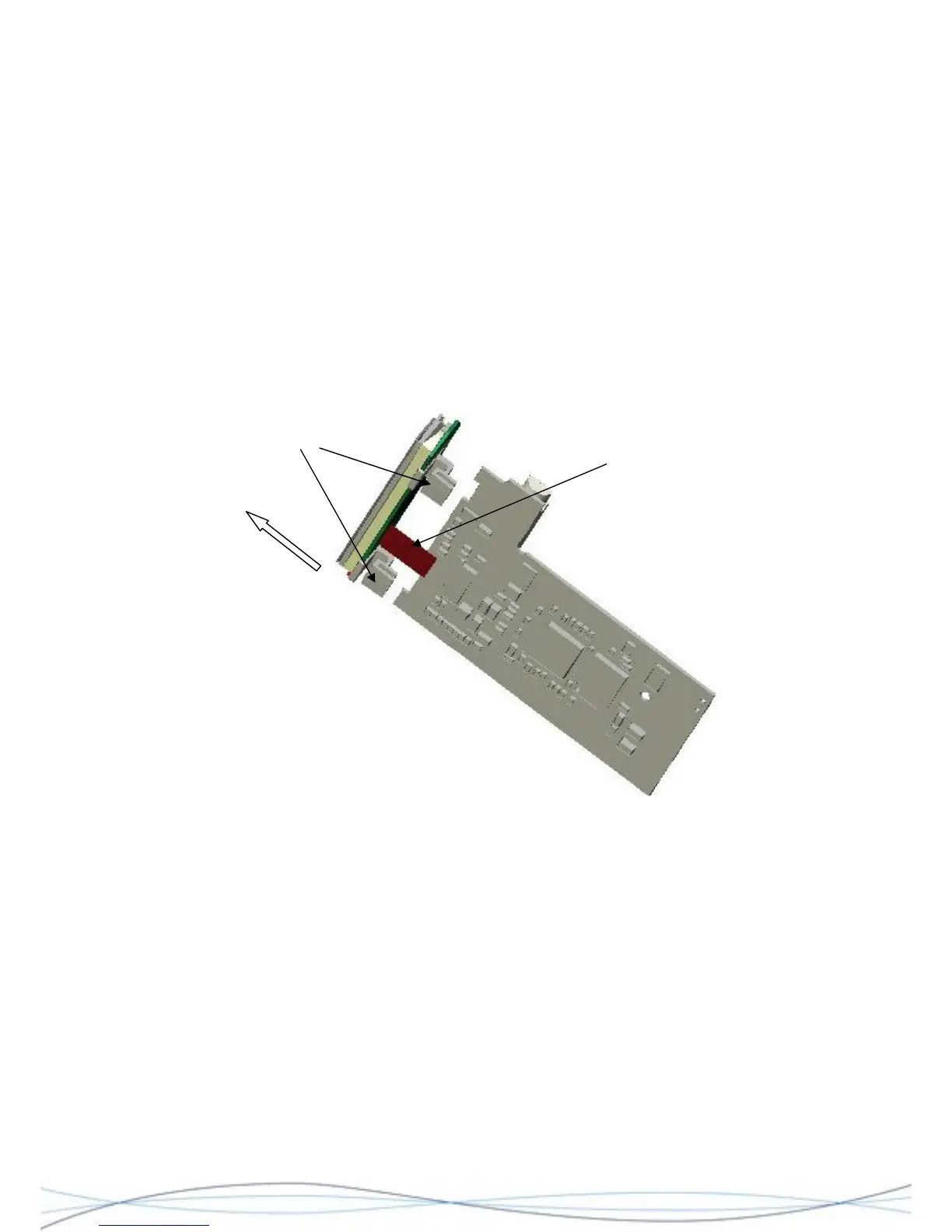
4.4.5 Display Removal
This whole assembly should be treated as a non-serviceable item, to be replaced in its
entirety.
The display module is held in place onto the decoder PCB, by two plastic clips. To remove
the display, hold the decoder PCB assembly in one hand and grip the edges of the
"release bar" on the flexible connecting strip connector, between your finger and thumb.
Pull the bar towards the display module until it "clicks", to release the connecting strip.
Grip and pull the display assembly away from the decoder PCB.
Grip display
assembly and
pull away from
decoder
Flexible connecting strip
Retaining clips
4.5 Servicing Information for the Decoder PCB’s 0261-7498 (MKI) & 0261-8243 (MKII)
The following information is intended to enable a series of front-line diagnostic tests on the
Decoder PCB, in order to establish the possible area at fault and whether a field-repair is
possible. Basic fault-finding information has been provided on the most common faults,
categorised by how the fault has been observed.
Please refer to the circuit and layout diagrams in Section 7.
4.5.1 Test Arrangement
It may be possible to check the Decoder PCB whilst it is still fitted to the rear-case
assembly and using the receiver's AA battery, but where it is necessary to remove the
PCB for access (see section 5.4.3), then separate power supply arrangements must be
made. Care should be taken not to damage the PCB contact areas, when making such
connections.
33