TM1215 Iss. 6.0 RPR750
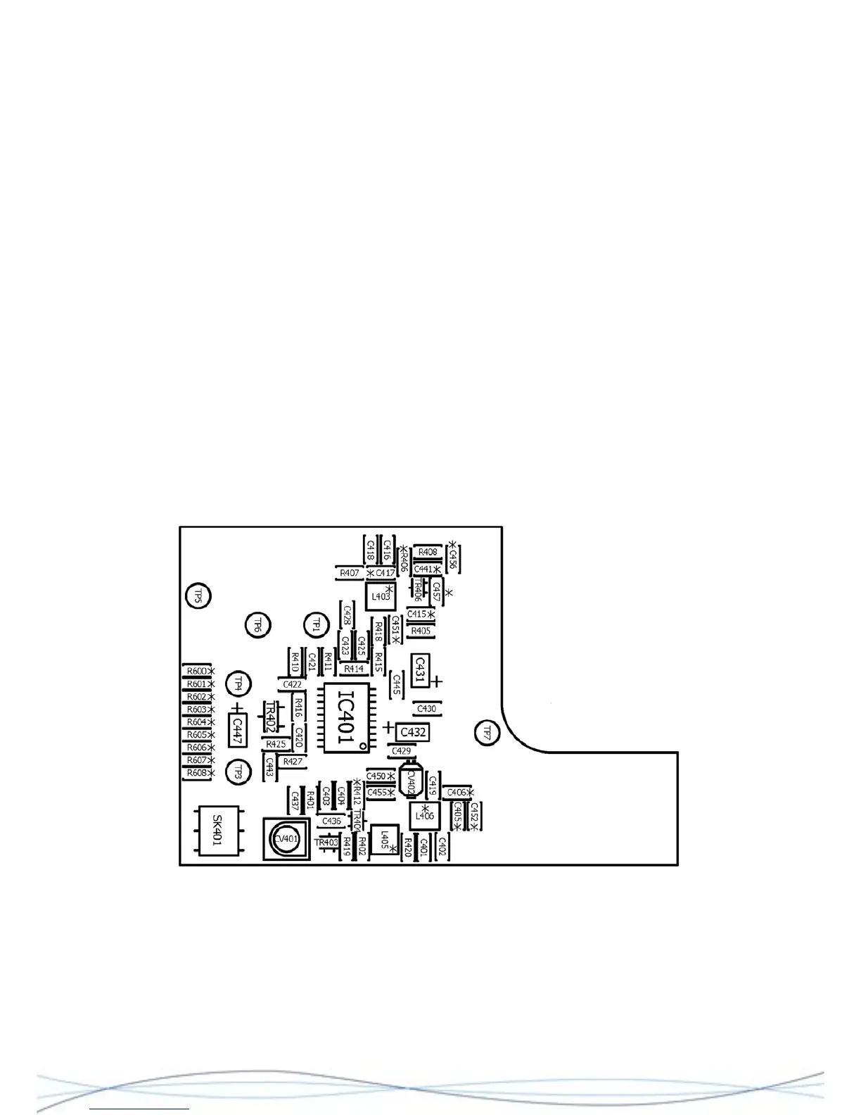
Starting with the radio PCB uncovered, connect the audio probe from the SINAD meter
between TP1 and Gnd./0V (the circular PCB track next to TP1 is the most suitable point).
Temporarily fit R416 (0R), or connect TP6 to TP7, to enable the receiver. Check the
battery voltage is correct (TP7) and also the 1V rail (TP4).
Adjust CV404 for the best SINAD signal. Reduce the RF output from the signal generator
to a lower level e.g. -60dBm and adjust CV402 and CV 403 for the best SINAD, whilst
further reducing the RF level as necessary.
Fit the case front and adjust CV 401 for best SINAD, gradually reducing the RF signal
level, as necessary.
Remove R416, TP6/TP7 link and any other connections made during this procedure.
Radio alignment is now complete.
4.7 Alignment of HF Radio PCB
4.7.1 Test Arrangement
The HF Radio may be aligned outside of the case assembly, but will need to be
connected to a working HF variant decoder and rear case assembly, with an AE1 ferrite
aerial and PL1 fitted. Power may be provided by the primary battery, or an external PSU
connected to the battery terminals. Any alignment must be done in an area free from
external RF signal interference.
Layout of HF Radio PCB, showing Test Points and Adjustment Trimmers
40