TM1215 Iss. 6.0 RPR750
4.5.14 Pager Clock is inaccurate
Check that the correct crystal (XL2) is fitted for the code format used. Confirm that the
frequency is within limits. If not, check C1 & C2 and replace the crystal if necessary.
4.6 Alignment of VHF & UHF Radio PCB's
It is possible to perform a rudimentary radio PCB alignment, outside of the case assembly.
However for final tuning of the aerial, it is necessary to use either a Multitone alignment
jig, or a modified case assembly, which has the necessary cut-outs for access to the
alignment points.
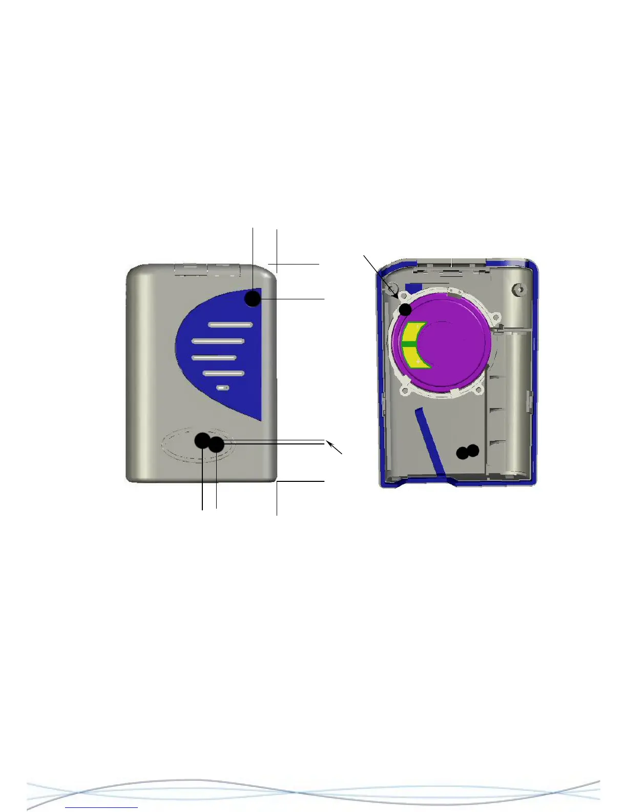
Hole through
loudspeaker
5 25
13
14
18
10
Dimensions are shown in millimetres and are approximate.
Diagrams showing hole positions for tuning points on a "dummy" case -front. The
suggested drilled hole diameter is 6 - 6.5mm. N.B. It is essential to retain the
loudspeaker on the inside of the case, as its metal construction forms an intrinsic
part of the circuit conditions, when fine-tuning the aerial. It will be necessary to
create a hole through the metal surround of the speaker.
4.6.1 Test Arrangement
In order to align a radio, the PCB will need to be connected to a working decoder PCB &
rear case assembly and the drilled front-case fitted over the radio for final tuning. Power
may be provided by an internal battery, or an external PSU connected to the battery
terminals. Any alignment must be carried out in an area, which is free from external RF
signal interference.
38