TM1215 Iss. 6.0 RPR750
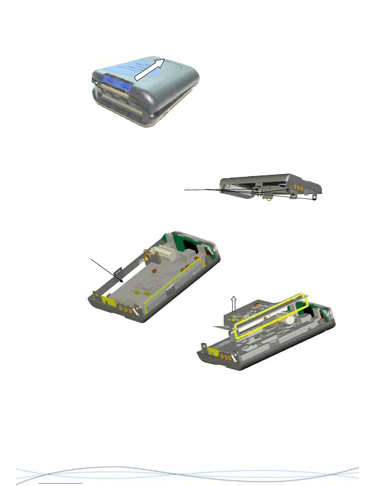
Separate the two case halves around the
area of the catches. Holding the rear half
of the pager in one hand, with the other hand, grip and gently pivot the case front
upwards. This should release the remaining 2 catches. Take care not to strain the speaker
connection. Using tweezers or fine pliers, unplug the loudspeaker connector from the
decoder PCB and put the case front assembly aside.
Location of "locking" catches on case-rear moulding
4.4.3 PCB Separation
NOTE: PCB profiles are illustrative only and may vary for each model of the RPR 750.
Lift here
To remove the radio PCB, gently lever-up the edge of the board at the point shown. This
will release the PCB assembly from the socket on the decoder PCB. Lift the PCB (taking
care not to damage the aerial loop) away from the housing.
To remove the decoder/display assembly from the case, firstly remove the rubber PCB
spacer. Remove the M2 retaining screw located where shown, using a cross-head (Pozi)
screwdriver. This will release the assembly, which may then be lifted from the housing.
31