TM1215 Iss. 6.0 RPR750
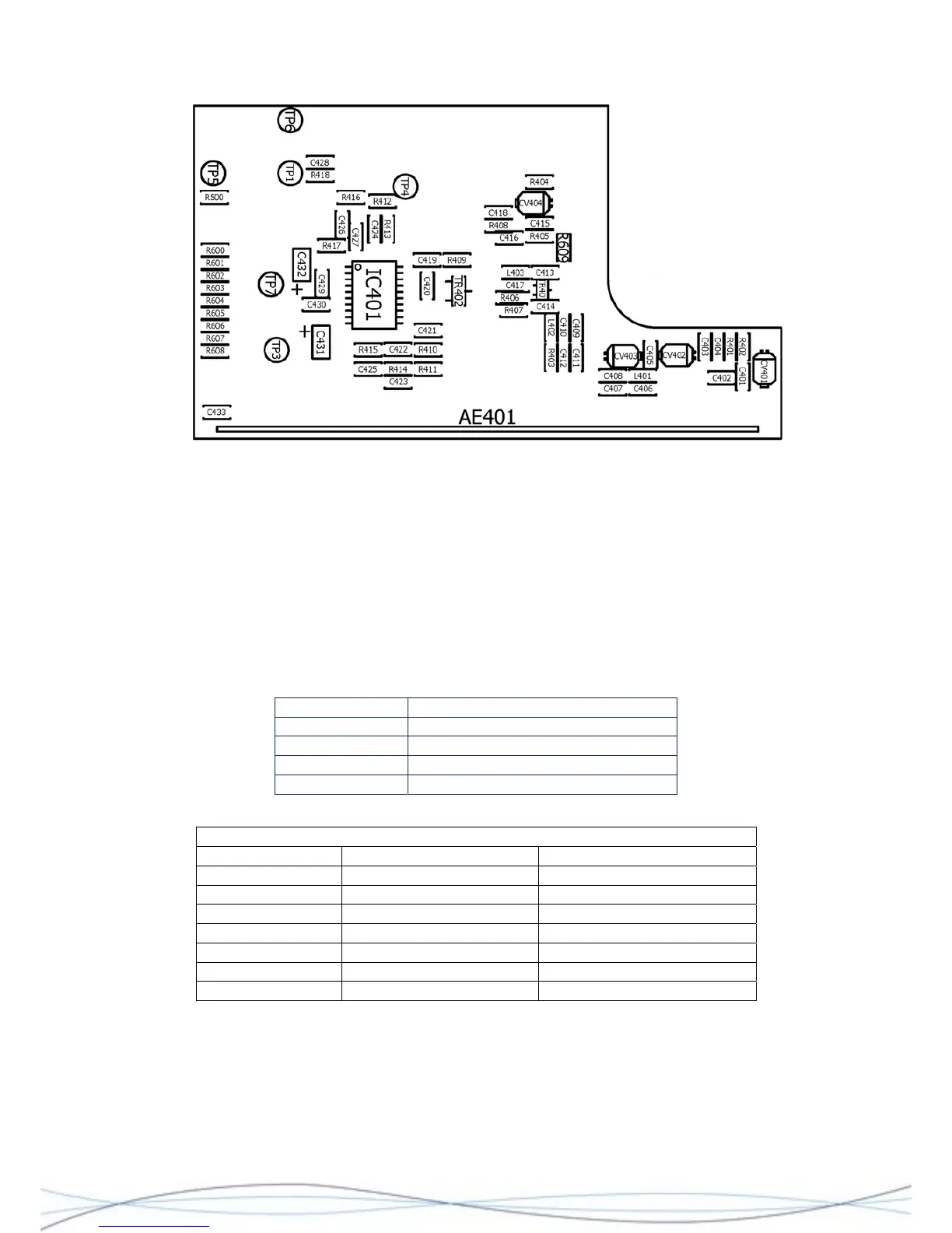
Layout of VHF/UHF Radio PCB, showing Test Points and Adjustment Trimmers
4.6.2 Test Equipment
RF signal generator, with external FM modulation I/P
SINAD Meter
Digital Multimeter
Ceramic/insulated Bladed Trimming Tool & Probe suitable for audio frequencies
Non-invasive coupling device for RF signal e.g. small telescopic aerial connected to RF
signal generator.
4.6.3 Tuning & Test Points
Tuning Points Description
CV401 Aerial Tuning
CV402 RF Stage/Image Filter Tuning
CV403 RF Stage/Image Filter Tuning
CV404 Fine Frequency Setting
Test Points
Test Point Signal Description
TP1 Audio 30mV Audio O/P
TP2 -
TP3 455kHz IF Signal
TP4 1.0V rail (-0.05/+0.1V) 1V regulated supply
TP5 0V Ground
TP6 Pull-up Rx enable RXEN Receiver Enable
TP7 1.1 - 1.6V dc Battery Positive
4.6.4 Procedure
Set the signal generator to the RF channel frequency and modulate the carrier with the
audio output from the SINAD meter. Set the FM deviation to the appropriate level for the
channel spacing of the PCB under test. Set the RF output to high e.g. +20dBm. Do not fit
the case-front at this stage.
39