Rev. 9-24-14 Part #15-10683
www.NabcoEntrances.com GT 710-8710 Swing Door System Low Energy Operator
Install the Header 3-9
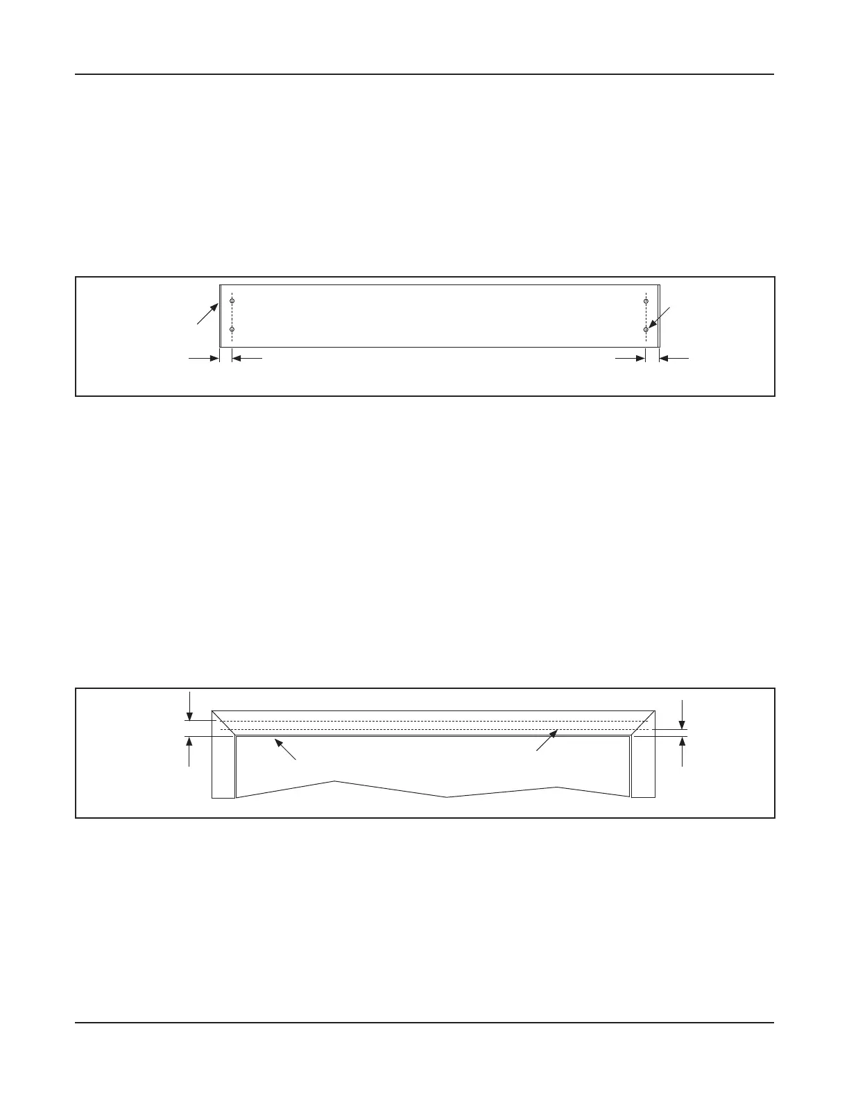
Measure 1 inch from the End Cap of Header towards the center. Mark a Vertical Line.
Measure at least 1/2 inch from the bottom of Header towards the top. Mark a Horizontal Line
the center of the second screw hole. Drill 1/4 inch screw hole.
a. It may be necessary to install a Shim behind the Header if mounting the Header to a wall.
Go to the Strike side of Header. Repeat steps 3 thru 5.
DN 1086
Pivot side of Header
1/4” Screw holes
1”
1”
Figure 3-2 Drill 1/4” Screw holes on both sides of Header
Secon 3c: Prepare the Door Frame
Go to the Pivot Side of Swing door.
Measure up from the Bottom edge of the Top door frame:
X GT 710: 1/8 inch
X GT 8710: 1-1/8 inch.
Mark a Horizontal Line on the face of Top door frame, at both ends. Please see .
DN 1109
Mark Measurement
across Top door frame
1/8”
(GT 710)
Top of Door
1-1/8”
(GT 8710)
Figure 3-3 Measure from the Top of Swing door to the Top Door Frame
Lift the Header up against the Top door frame until the bottom edge of Header is butted up
against the Horizontal Line, at both ends. Please see .
To ensure proper operation of the Swing Arm:
X
the outside edge of the Pivot Door Jamb.
X For a Door Jamb that is wider than 1-3/4 inches, measure from the inner edge of the Pivot
Door Jamb to the center. Mark a vertical line at the 1-3/4 inch measurement. The Pivot side
of Header must butt against the 1-3/4 inch mark.