Rev. 9-24-14 Part #15-10683
www.NabcoEntrances.com GT 710-8710 Swing Door System Low Energy Operator
Install the Second Half of Swing Arm 6-19
DN 0023
DN 0022
RIGHT HAND INSWING
LEFT HAND OUTSWING
DN 1134
EED
CHECK
BACK CHECK
2
1
3
4
4
12
3
For Commercial or Industrial Use
Manufactured
Pedestrian Commercial & Industrial
Commande de porte pietonniere a
60 Hz
S82 W18717 Gemini Driv
e
Muskego, WI 53150 USA
Pedestrian Door Operator
usage commercial ou industriel
TL
Model No.
NABCO
ENTRANCES
115 Volts
Amps
Ma
x
501 S
in
LISTED
2
1
3
4
3
2
1
4
BACK CHECK
MAIN SPEED
LATCH CHECK
For Commercial or Industrial Use
Manufactured
Pedestrian Commercial & Industrial
Commande de porte pietonniere a
60 Hz
S82 W18717 Gemini Drive
Muskego, WI 53150 USA
Pedestrian Door Operator
usage commercial ou industriel
TL
Model No.
NABCO
ENTRANCES
115 Volts
Amps
Max
501 S
in
LISTED
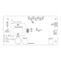
Figure 6-3 Preload: Inswing Arm
For Commercial or Industrial Use
Manufactured
Pedestrian Commercial & Industrial
Commande de porte pietonniere a
60 Hz
S82 W18717 Gemini Drive
Muskego, WI 53150 USA
Pedestrian Door Operator
usage commercial ou industriel
TL
Model No.
NABCO
ENTRANCES
115 Volts
Amps
Max
501 S
in
LISTED
MAI
LATCH CHEC
BACK CHECK
2
1
3
4
4
12
3
MAIN S
LATCH CHEC
For Commercial or Industrial Use
Manufactured
Pedestrian Commercial & Industrial
Commande de porte pietonniere a
60 Hz
S82 W18717 Gemini Drive
Muskego, WI 53150 USA
Pedestrian Door Operator
usage commercial ou industriel
TL
Model No.
NABCO
ENTRANCES
GYRO TECH
115 Volts
Amps
Max
501 S
in
R
LISTED
R
BACK CHECK
2
1
3
4
3
2
1
4
DN 1129
DN 0024
DN 0025
RIGHT HAND INSWING
0 REVEAL
LEFT HAND INSWING
0 REVEAL
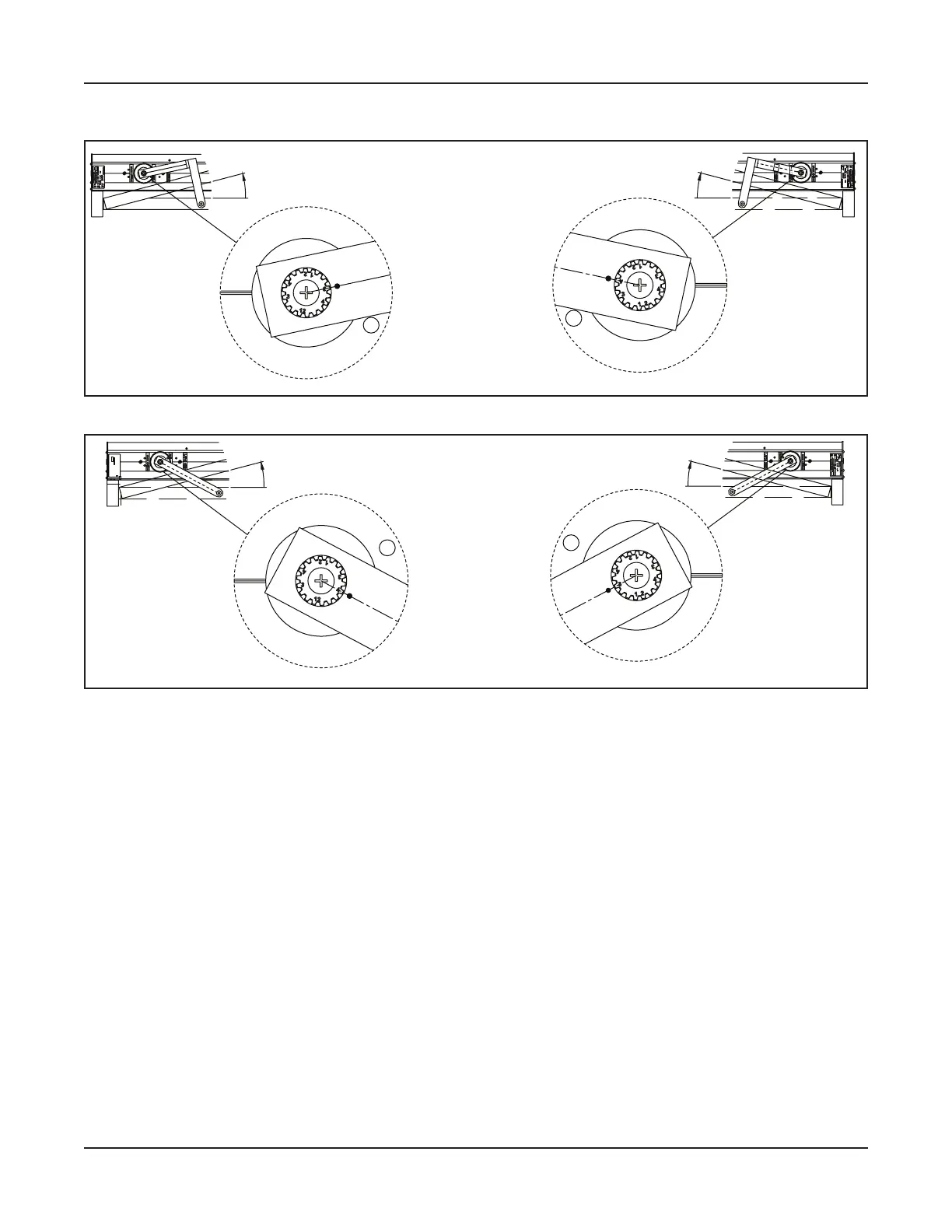
Figure 6-4 Preload: Inswing Arm with Zero Reveal
Secure the Swing Arm to the Operator Spindle with (1) Set Screw. Tighten but do not overtighten.
a. Ensure the Set Screw is seated correctly within the groove on the Operator Spindle.
Secon 6 b: Secure the Swing Arm to the Swing Door
6.b.a: Outswing Arm
Align the screw hole at the end of Swing Arm to the Rod End screw hole. Please see .
Pull the Swing Arm towards the Rod to connect.
Secure the Swing Arm to the Threaded Rod with (1) 3/8”-24 x 1-1/4” Socket Screw, (1) .405 Washer,
and (1) 3/8”-24 Lock Nut.
 Loading...