GT 710-8710 Swing Door System Low Energy Operator www.NabcoEntrances.com
Part #15-10683 Rev. 9-24-14
9-26 Install the Arm Stop
CHAPTER 9: INSTALL THE ARM STOP
Power must be turned OFF while installing the Arm Stop.
Do Not drill screw holes for the Arm Stop into the Motor/Operator!!!
Turn Power OFF.
Manually open the Swing Door 90 degrees. Please see .
Obtain the Parts Bag that includes (1) Arm Stop and (2) 1/4-20 x 1 inch Self Tapping screws.
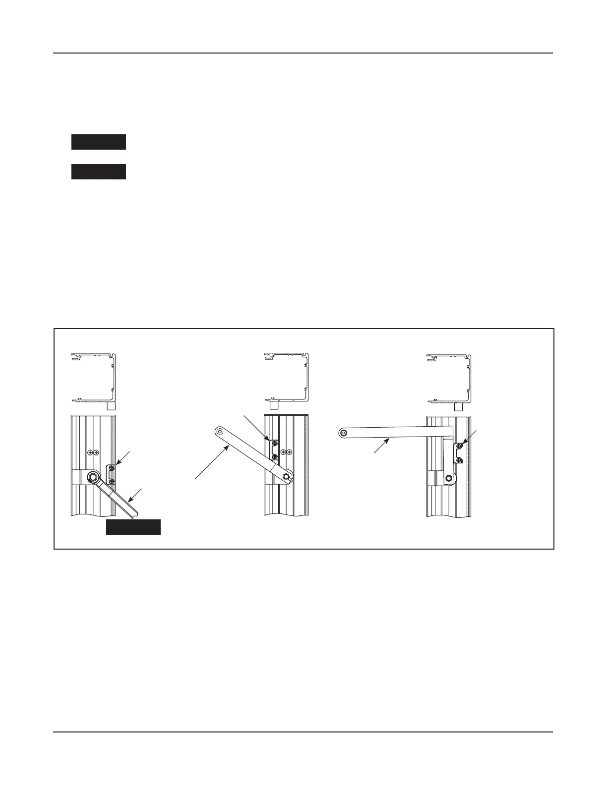
Position the Arm Stop at the bottom of Header according to type of Swing Arm and Reveal shown
in .
Use the Arm Stop as a template to mark and drill (2) 7/32 inch diameter screw holes.
Secure the Arm Stop with (2) 1/4-20 x 1 inch Self Tapping screws.
DN 1064
INSWING ARM
0 1/4” REVEAL
INSWING ARM
GREATER THAN 1/4” REVEAL
OUTSWING ARM
Outswing
8400
8500
8710
Inswing
8400
8500
8710
Inswing
8400
8500
8710
Posi on Arm Stop as shown.
Drill (2) 7/32” diameter holes.
Fasten with (2) 1/4-20 screws.
Posi on of Swing Arm
when Swing door is
opened to desired posi on.
Posi on Arm Stop as shown.
Drill (2) 7/32” diameter holes.
Fasten with (2) 1/4-20 screws.
Posi on Arm Stop as shown.
Drill (2) 7/32” diameter holes.
Fasten with (2) 1/4-20 screws.
Posi on of Swing Arm
when Swing door is
opened to desired posi on.
Remove Operator before drilling holes for Arm Stop.
CAUTION
Figure 9-1