Rev. 9-24-14 Part #15-10683
www.NabcoEntrances.com GT 710-8710 Swing Door System Low Energy Operator
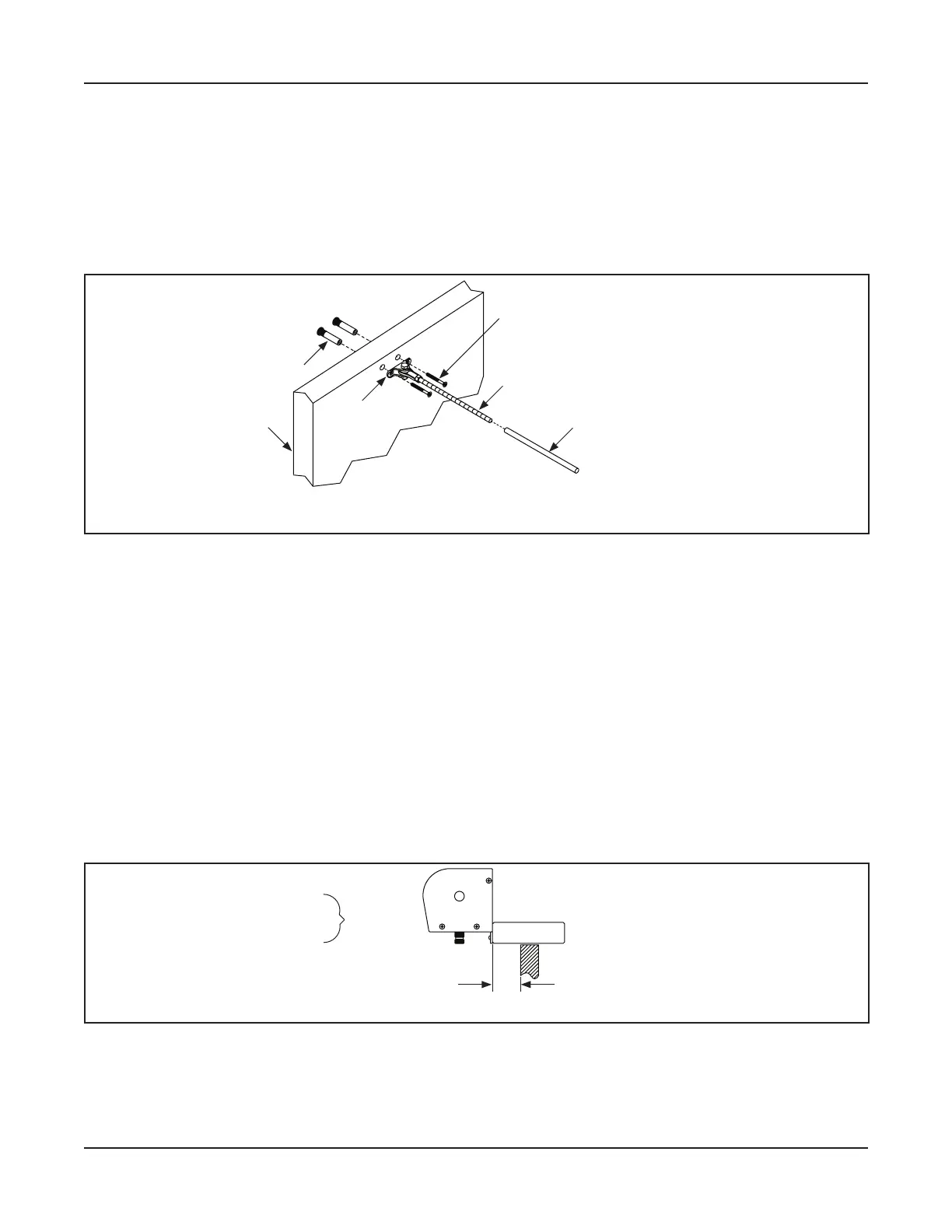
Install the First Half of Swing Arm 5-15
Cut the Plastic Tube to the same length as the exposed Rod (between the Links and Nuts).
Slide the Plastic Tube over the Threaded Rod.
Replace the Rod Link back onto the Threaded Rod.
Tighten the Nut against the Link to prevent the Rod from screwing In or Out.
DN 1097
Arm
Shoe
Sex Bolt
Threaded Rod
1/4-20 x 2-1/4”
Phillips Head Screw
Swing Door
Color Coordinated Sleeve
Figure 5-5 Secure Arm Shoe to the Swing Door
5.a.c: Secure the Arm Shoe to the Swing Door
see .
Ensure the Arm Shoe is square and level.
Use the Arm Shoe as a Template to mark the second Sex Bolt hole. Set aside.
Drill (2) 3/8 inch bolt holes all the way through the Swing door.
Go to the back of the Swing door. Insert each Sex Bolt into the drilled holes.
Go to the front of the Swing door. Secure the Arm Shoe to the Swing Door with (2) 1/4-20 x 2-1/4”
Screws.
Secon 5 b: Inswing Arm
Face of Swing Door
Back of Header
= Reveal
Figure 5-6 What is Reveal?
5.b.a: Prep the Swing Door
degrees
Go to or to measure the distance from the inside edge of the Pivot Door Jamb,