GT 710-8710 Swing Door System Low Energy Operator www.NabcoEntrances.com
Part #15-10683 Rev. 9-24-14
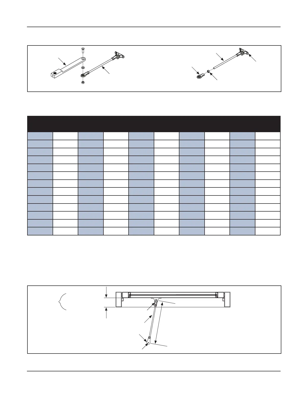
5-14 Install the First Half of Swing Arm
DN 1117
Rod End
Threaded Rod
Swing Arm
Nut
Threaded Rod
Arm Shoe
Figure 5-3 Disassemble the Outswing Arm
Go to to locate the appropriate length measurement for the Threaded Arm.
Table 5-2 Dimension “B” Rod Length
Rod Rod Rod Rod Rod
Reveal Length Reveal Length Reveal Length Reveal Length Reveal Length
0” 16-5/8”
3-1/4” 19-1/8” 6-1/2” 21-3/4” 9-3/4” 24-5/8” 13 27-1/2”
1/4” 16-13/16”
3-1/2” 19-5/16” 6-3/4” 22” 10 24-13/16” 13-1/4” 27-3/4”
1/2” 17”
3-3/4” 19-1/2” 7” 22-3/16” 10-1/4” 25” 13-1/2” 28”
3/4” 17-3/16”
4” 19-11/16” 7-1/4” 22-7/16” 10-1/2” 25-1/4” 13-3/4” 28-3/16”
1” 17-3/8”
4-1/4” 19-7/8” 7-1/2” 22-5/8” 10-3/4” 25-1/2” 14 28-7/16”
1-1/4”
17-9/16” 4-1/2” 20-1/8” 7-3/4” 22-7/8” 11 25-3/4” 14-1/4” 28-5/8”
1-1/2”
17-3/4” 4-3/4” 20-5/16” 8” 23” 11-1/4” 25-15/16” 14-1/2” 28-7/8”
1-3/4”
17-15/16” 5” 20-1/2” 8-1/4” 23-1/4” 11-1/2” 26-3/16” 14-3/4” 29-1/8”
2” 18-1/8” 5-1/4” 20-3/4” 8-1/2” 23-1/2” 11-3/4” 26-3/8” 15 29-3/8”
2-1/4” 18-5/16” 5-1/2” 20-15/16” 8-3/4” 23-3/4” 12 26-5/8” 15-1/4” 29-9/16”
2-1/2” 18-1/2” 5-3/4” 21-1/8” 9” 24” 12-1/4” 26-13/16” 15-1/2” 29-13/16”
2-3/4” 18-11/16” 6” 21-3/8” 9-1/4” 24-3/16” 12-1/2” 27-1/16” 15-3/4” 30”
3” 18-7/8” 6-1/4” 21-9/16” 9-1/2” 24-3/8” 12-3/4” 27-5/16” 16 30-1/4”
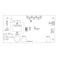
Measure the Threaded Rod between the center of each Eye, located on each Link, located at each end
of the Rod. Please see Dim B in .
Remove the Link that is not attached to the Arm Shoe, from the Threaded Rod. Please see
.
Cut the Threaded Rod according to the measurement that was determined in Step 3.
Face of Swing Door
Dim. B
Back of Header
Reveal =
Arm
Link
Link
Figure 5-4 Measure the Threaded Rod Length
Obtain (1) color coordinated Plastic Tube from the Outswing Rod assembly. Please see .