Rev. 9-24-14 Part #15-10683
www.NabcoEntrances.com GT 710-8710 Swing Door System Low Energy Operator
Install the First Half of Swing Arm 5-13
CHAPTER 5: INSTALL THE FIRST HALF OF SWING ARM
Secon 5 a: Outswing Arm
FOR INSWING ARMS SKIP TO
SECTION 5 B
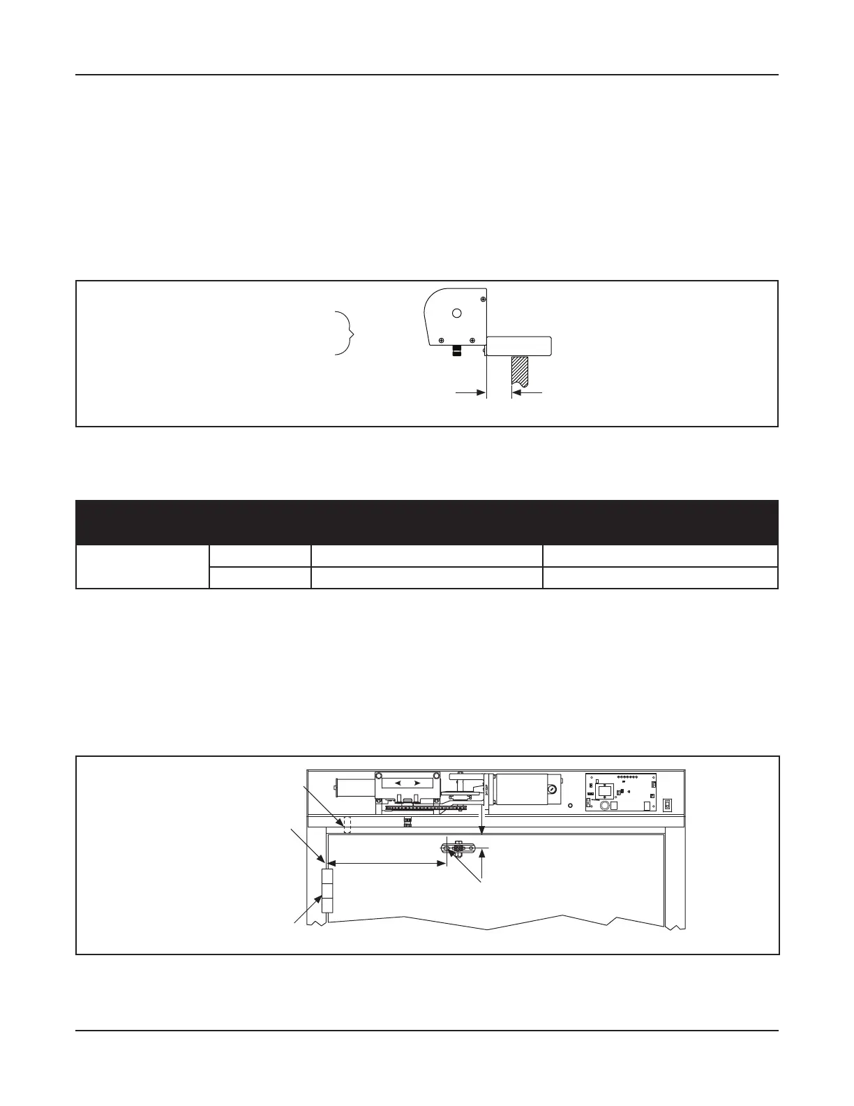
Face of Swing Door
Back of Header
= Reveal
Figure 5-1 What is Reveal?
5.a.a: Prep the Swing Door
Table 5-1 Dimension “A” Arm Shoe Mounting Locations
Outswing
Model Pivot Type With Fingerguard No Fingerguard
GT 710 & 8710 Butt/Offset
N/A 16-15/16”
Center Pivot
N/A 16-15/16”
Go to to measure the distance from the inside edge of the Pivot Door Jamb, or the Center
.
Mark a Vertical line on the face of the Swing door.
At the Vertical line, measure 1-1/2 inches from the top edge of the Swing door down to the center of
the Swing Door.
DN 1112
1-1/2”
Dim. A
Center mark for
fi rst Sex Bolt Hole
ON
LED
TRANSFORMER
O
F
F
12
AUX
PWR
4
J2
3
J5
AC IN
F2
SW2
SW1
F1
RELAY
RELAY
J4
TDAS
SIGNAL
INPUT
TDPG
LCHK
CLOSE
Fuse 1: 0.5A 24 VAC
STOP
OPEN
BCHK
CURRENT
LIMIT
MOTOR
J1
R28
MAGNUM 4A
Fuse 2: 5A 120/240
Capacitor
MOV
BACK
CHECK
SWITCH
DOOR
CLOSED
SWITCH
FOR
XXX HAND
UNITS
Center Pivot
Bu /Off set
(Inner Edge of Door Jamb)
Bu Hinge
Figure 5-2 Measure to Mark First Sex Bolt Screw hole
5.a.b: Prep the Outswing Arm Assembly
Remove the Swing Arm from the Threaded Rod. Set aside. Please see .