EasyManua.ls Logo

Nabco GT1175 User Manual

Default Icon
62 pages
To Next Page IconTo Next Page
Page #1 background imageLoading...
Page #1 background image
1 of 62
Model GT1175 Standard and Pocketed Slide Doors Installaon Manual
**with Opus Controller**
P/N C-00370 Rev 11-12-20
NABCO Entrances Inc. S82 W18717 Gemini Drive Muskego, Wisconsin 53150
Phone: (877) 622-2694 Fax: (888) 679-3319 www.nabcoentrances.com
NABCO hours of Operaon: Monday to Friday 8:00 a.m.- 4:30 p.m. (Central Time)
Associated Manuals Part Numbers:  OPUS Wiring and Programming Manual P/N C-00139
Automatic Sliding Door Owners Manual (P/N C-00109) for Decal Installation
NABCO Price Book P/N 16-9244-30 (for Sensors, Switches, and Accessories)
Turn OFF all power to the Automatic Door if a Safety System is not working.
Instruct the Owner to keep all power turned OFF until corrective action can be achieved
by a NABCO trained technician. Failure to follow these practices may result in serious
consequences.
NEVER leave a Door operating without all Safety detection systems operational.
WARNING
Table of Contents
 4
 4
 5
SECTION 3.1: To the Installer .......................................................................5
SECTION 3.2: Objecve ...........................................................................5
 5
SECTION 4.1: Request a User Name/Password to gain access into the “myNABCO” portal . . . . . . . . . . . . . . . . . . . . 5
SECTION 4.2: Associated Video QR Code Link .........................................................5
SECTION 4.3: Types of Units .......................................................................5
SECTION 4.4: Feature Comparison between Controls ...................................................6
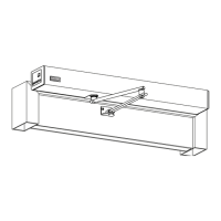
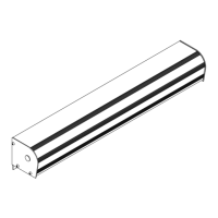
SECTION 4.5: Header Components ..................................................................6
 6
 7
  8
SECTION 7.1: Secure Transom Vercals to Header .....................................................8
SECTION 7.2: Install the Glass Stops .................................................................9
SECTION 7.3: Secure Header and Transom to Pocketed Jamb Tubes ......................................11
SECTION 7.4: Assemble the Door Frame ............................................................11
SECTION 7.5: Install the Tie Rods ..................................................................12
 
SECTION 8.1: Anchor Placements ..................................................................13
SECTION 8.2: Complete the Tie Rod Installaon (For Transom Units only) .................................14

Table of Contents

Other manuals for Nabco GT1175

Questions and Answers:

Nabco GT1175 Specifications

General IconGeneral
BrandNabco
ModelGT1175
CategoryDoor Opening System
LanguageEnglish

Summary

Chapter 1: Warning Labels

Chapter 2: General Safety Recommendations

Chapter 3: Scope

Section 3.1: To the Installer

Familiarizes the installer with proper installation and operation procedures.

Section 3.2: Objective

Details the GT1175 system's design, controlled by the Opus Control.

Chapter 4: Getting Started

Section 4.1: Request a User Name/Password to gain access into the "myNABCO" portal

Instructions for accessing the myNABCO portal for user credentials.

Section 4.2: Associated Video QR Code Link

Provides a QR code link for locating service parts on the NABCO website.

Section 4.3: Types of Units

Describes the two main mechanical configurations: Single Slide and Bi-Part.

Chapter 5: Before Assembling Door Frame

Section 5.1: Inspect the Rough Opening

Instructions for inspecting the rough opening size and levelness.

Chapter 6: Assemble Door Frame (No Transom)

Chapter 7: Assemble Door Frame With Transom

Section 7.1: Secure Transom Verticals to Header

Steps to attach transom clips and verticals to the header.

Chapter 8: Secure Door Frame to Building

Section 8.1: Anchor Placements

Guidelines for anchor placement in jambs, transom, and header.

Chapter 9: Wire the Switch Assembly (Rocker Switch or Key Switch)

Chapter 10: Install the Threshold

Section 10.1: Install the Surface Threshold

Instructions for installing the surface threshold.

Section 10.2: Install the Recessed Threshold

Instructions for installing the recessed threshold.

Chapter 11: Install the Interior Full Open Sidelite (Pocketed)

Section 11.1: Install the Bottom Pivot

Steps to install the bottom pivot for the sidelite.

Chapter 12: Install the Exterior Full Open Sidelite (Standard & Pocketed)

Section 12.1: Install the Bottom Pivot

Steps to install the bottom pivot for exterior sidelite.

Section 12.2: Partially Install the Limit Arm

Initial steps to install the limit arm.

Section 12.3: Install the Full Open Sidelite onto the Upper Pivot and Bottom Pivot

Mounting the sidelite onto the header and floor pivots.

Section 12.4: Complete Installation of the Limit Arm

Final steps for limit arm installation.

Section 12.5: Adjust the Ball Detents

How to adjust ball detents for breakout resistance.

Chapter 13: Install the Fixed Sidelite (Standard and Pocketed)

Section 13.1: Secure the Fixed Sidelite to the Door Frame

Steps to secure the fixed sidelite to the door frame using mounting brackets.

Section 13.3: Install the Floor Bracket

Mounting the floor bracket to the strike stile and floor.

Chapter 14: Install the Slide Door

Section 14.1: Secure Slide Door to Belt Clips

Attaching the slide door to the belt clips.

Section 14.2: Install Bottom Guide to Slide Door

Installing the bottom guide to the slide door.

Section 14.3: Adjust Rollers

Adjusting hanger and anti-rise rollers for proper door operation.

Section 14.4: Adjust the Interlocks

Adjusting interlocks for proper door closure.

Chapter 15: Permanently Install the Threshold

Section 15.1: Secure Threshold to Floor

Securing the threshold to the floor.

Chapter 16: 110 VAC General Wiring

Chapter 17: Install Weathering

Section 17.1: Door Panels

Securing brush holders to door panels for weathering.

Section 17.2: Door Frame

Applying caulking to the door frame and threshold.

Chapter 18: Glazing

Section 18.1: Door Panel

Instructions for installing glass panels into door frames.

Section 18.2: Complete the Transom Installation

Steps for completing transom glass installation.

Section 18.3: Complete the 1/4" Glass Stop Flush Glazing

How to complete flush glazing with glass stops.

Section 18.4: Dust Protector Hoods (Clean Room Optional)

Installation of dust protector hoods for clean room applications.

Section 18.5: Aluminum Hood

Installation instructions for aluminum hoods.

Section 18.6: Stainless Steel Hood (Header)

Installation instructions for stainless steel header hoods.

Chapter 19: Adjustments

Section 19.1: Adjust Horizontal Position of Carrier

Steps to adjust the carrier's horizontal position.

Section 19.2: Balance Weight of Door Panel with Nose Caster

How to balance door panel weight using nose casters.

Section 19.3: Adjust the Breakout Magnet

Adjusting the breakout magnet for proper function.

Section 19.4: Adjust Preload

Adjusting the preload for door sag.

Section 19.5: Adjust the Ball Plunger

Adjusting the ball plunger for breakout resistance.

Chapter 20: Slide Door Safety Check

Chapter 21: Pocketed Slide Door Configuration

Section 20.1: Full Open Pocketed Slide Door

Configuration steps for full open pocketed slide doors.

Section 20.2: Fixed Sidelite Pocketed Slide Door

Configuration steps for fixed sidelite pocketed slide doors.

Service Parts: Non-Handed Kit P/N A-00407

Service Parts: LH Kit P/N A-00403; RH Kit P/N A-00618

Service Parts: Non-Handed Kit; Full Open Standard

Service Parts: Header

Service Parts: Fixed Sidelite

Service Parts: Left Hand Fixed Sidelite

Service Parts: Right Hand Fixed Sidelite

Service Parts: Slide Door for Fixed Sidelite

Service Parts: Left Hand Slide Door Fixed Sidelite

Service Parts: Right Hand Slide Door Fixed Sidelite

Service Parts: Full Open Sidelite

Service Parts: Left Hand Sidelite Full Open

Service Parts: Right Hand Sidelite Full Open

Service Parts: Slide Door Full Open

Service Parts: Left Hand Slide Door Full Open

Service Parts: Right Hand Slide Door Full Open

Service Parts: Glass Stops and Transom Hardware

Related product manuals