8 of 62
GT1175 Standard and Pocketed Slide Doors Installaon Manual; with Opus Controller www.NabcoEntrances.com
P/N C-00370 Rev 11-12-20
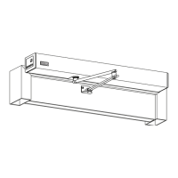
2. Orientate the Frame in relaon to the building:
X
X
3. Secure the Header to each Jamb Tube with (6) 1/4-20 x .75 Whizlock screws.
a. If installed correctly there will be a 1/8 inch gap between the boom of Jamb Tubes and the at surface.
Jamb Tube
DN 1349
Header
1/4-20 x .75”
Whizlock Screw
1/8” gap
Figure 4
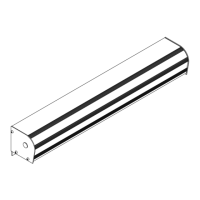
DN 0688
Fixed or Breakout Panel
Slide Door
Header
Transom Horizontal
Transom Ver cal
Glass or Panel
Jamb Tube
Figure 5
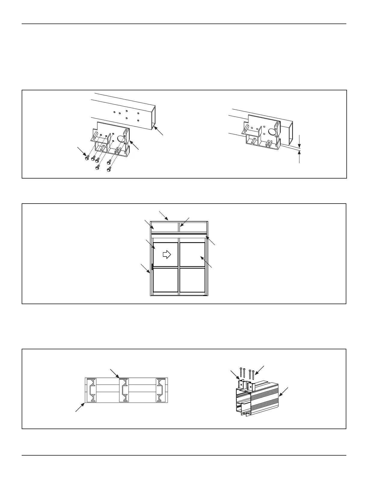
1. Place the Header on a at surface. Align the Transom clips to the pre-drilled holes on top.
2. Secure Transom Clips to Header with 10 x 1-3/4 inch Phillips Pan Head screws.
a. Please refer to the orientaon scker located on the Header for proper locaon and orientaon.
DN 0419
Top of Header
Orienta on S cker
Ver cal Transom Clip
10x1-3/4”
Pan Head Screw
HEADER COVER SIDE
Header Cover
3. Obtain Transom Vercals.
4. Secure (1) Transom Vercal to each Transom Clip with 1/4-20 x 1” Flat Head screws.
Figure 6
 Loading...