22 of 62
GT1175 Standard and Pocketed Slide Doors Installaon Manual; with Opus Controller www.NabcoEntrances.com
P/N C-00370 Rev 11-12-20
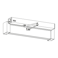
1. Locate (2) Cut Outs on the side of the Pivot Sle. Align and then slide the Fixed Sidelite unl (2) Mounng Brackets (pre-
installed on the Pivot Jamb Tube) can be seated inside each Cut Out.
2. Slide the Fixed Sidelite towards the Interior of the Building unl both Mounng Brackets bu up against the inside wall of
the Pivot Sle.
Figure 46
DN 0863
Jamb Tube Moun ng Bracket
Header Moun ng Bracket
(Inside Ver cal Mullion)
1/4-20 x 1/2”
Flat Head Screw
1/4-20 x 1/2”
FlatHead Screw
Jamb Tube
Moun ng Bracket
Cutout Clearance
3. Locate (1) cut out at the top of Strike Sle. Align and then slide the Fixed Sidelite unl (1) mounng bracket (pre-installed
under the Boom Lip of Header) can be seated inside the Cut Out.
Figure 47
DN 0862
Cut Out
Moun ng Bracket
Strike S le
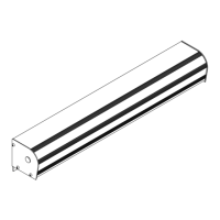
4. Snap a chalk line between Jamb Tubes in front of Sidelite Panel. If the Sidelite Panel is ush to the chalk line, it is square.
5. Secure the Fixed Sidelite Panel to all (3) Mounng Brackets with 1/4-20 x 1/2 inch Flat Head Screws.
Figure 48
DN 0624
Chalk Line
Jamb Tube
Fixed Panel
Jamb Tube
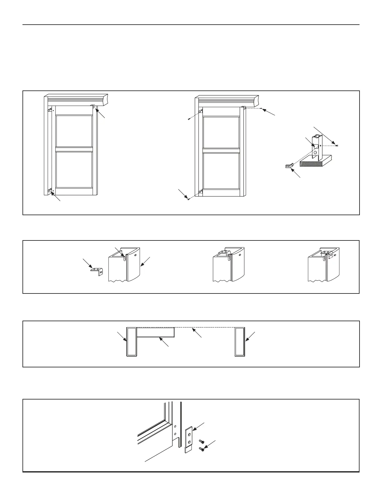
1. Go to the boom of Strike Sle. Remove the Boom Guide Cover Plate.
DN 0128
Bo om Guide
Cover Plate
1/4-20 x 3/4”
Phillips Screw
Figure 49
 Loading...