12 of 62
GT1175 Standard and Pocketed Slide Doors Installaon Manual; with Opus Controller www.NabcoEntrances.com
P/N C-00370 Rev 11-12-20
Note: Tie Rods are provided for Transom Units as required by NABCO Engineering.
1. Li to posion the assembled Frame into the rough opening.
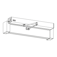
2. Shim and Plumb Jamb Tubes in both planes to ensure the rough opening allows a 1/4 inch clearance.
3. Shim and plumb the Transom Horizontal at the top to ensure the rough opening allows a 1/4 inch clearance.
Figure 15
1/4” Shim and plumb
for proper clearance
DN 1348
Jamb Tube
Horizontal
Transom
1/4”
Header
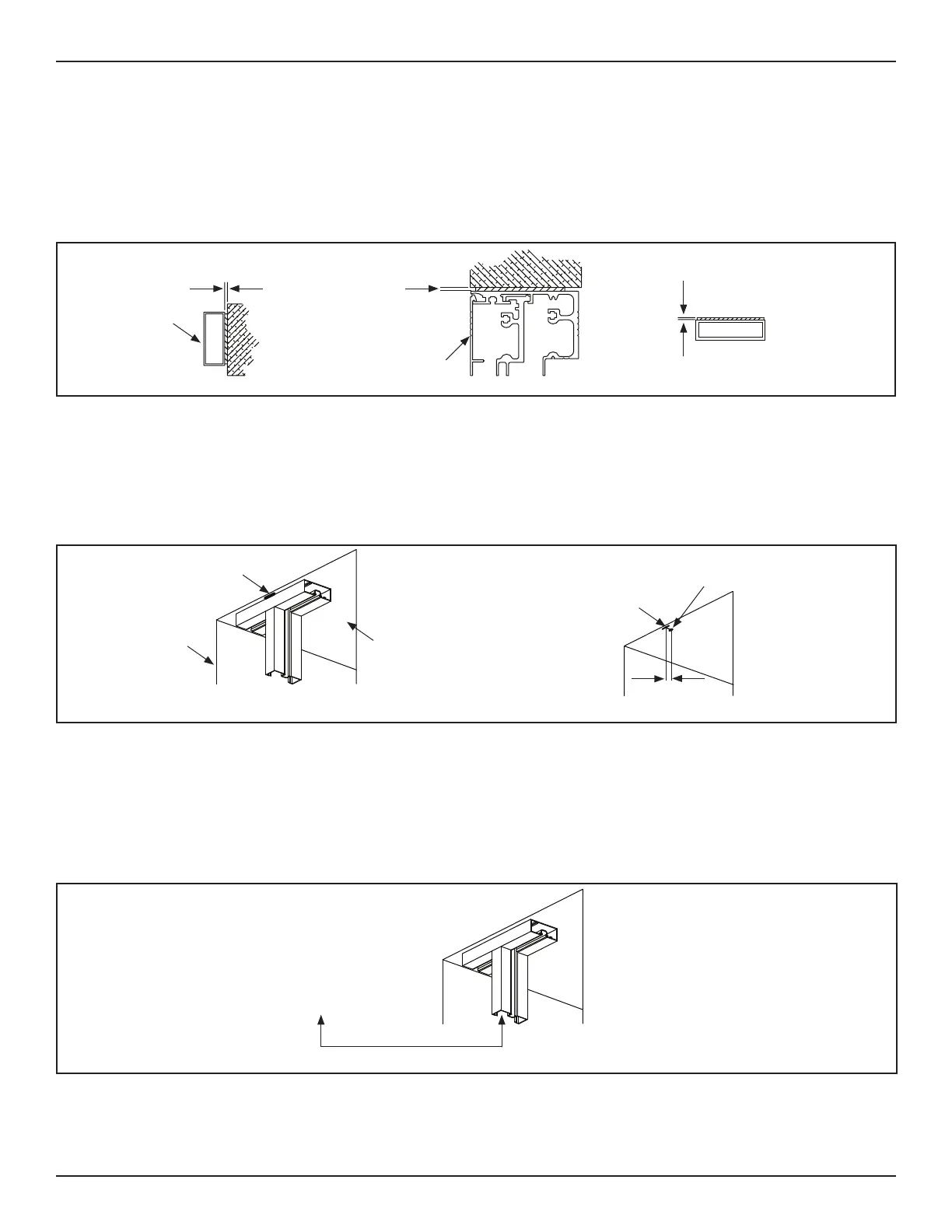
4. Go to the side of Header that is closest to the Exterior side of Door Opening,
5. Mark the exact locaon of each Transom Vercal by drawing a horizontal line (the full width of the Transom Vercal); along
the outside edge of the Transom Horizontal; onto the ceiling of the Rough Opening.
a. Do not draw the line wider than the Transom Vercal. It is recommended to use a level for this step.
6. From the center of each Horizontal line, measure 1 inch deep (towards the interior side of building). Mark a Vercal line
onto the ceiling of the Rough Opening. It is recommended to use a level for this step.
Mark Line
Ceiling
DN 0411
Measure 1” deep from
center of Horizontal Line
1”
3/8-16 Concrete Anchor
hole end of 1” mark
Exterior side of
Door Opening
Figure 16
7. Carefully remove the Door Frame from the Rough Opening. Set aside.
8. At the end of each Vercal Line mark, drill (1) 3/8-16 Concrete Anchor hole into the ceiling of the Rough Opening.
9. Obtain all Tie Rods. (1) Tie Rod Parts box is shipped for each Transom Vercal.
10. Snap the Back Plate out from each Transom Vercal for easy access to the Tie Rod.
11. Transom Vercals are pocketed with (2) channels. Determine which channel is closest to the Exterior side of Door Opening.
12. Insert (1) Tie Rod into that channel.
Channel closet to
Exterior side of Door Opening
DN 1350
Figure 17
13. Go to the top of Header. Insert each Tie Rod down into the 1 inch, pre-drilled hole.
14. Once the Tie Rod is through the Header, loosely aach (1) Backing Plate, (1) 3/8 inch Washer, (1) 3/8 inch Lock Washer and
(1) 3/8-16 Hex Nut (in that order) to the boom of the Tie Rod.
a. Length of each Tie Rod equals the distance between the top of the Header, and top of Transom Horizontal, plus 2-5/8”.
 Loading...