25 of 62
www.NabcoEntrances.com GT1175StandardandPocketedSlideDoorsInstallaonManual;withOpusController
Rev.11-12-20 P/NC-00370
DN 0894
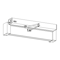
Li Up
Bo om Guide; Prongs
Guide Channels
Figure 57
1. Go to the Boom Rail on the Fixed Sidelite. Locate the Bracket that should be scking out from underneath.
2. Slide the Pivot Sle (on Slide Door) onto the Bracket.
3. Support the weight of the Fixed Sidelite. Breakout the Slide door to Full Open posion.
4. Secure the Bracket to the Pivot Sle with (2) 1/4 - 20 x 3/4 inch Whiz-Lock screws
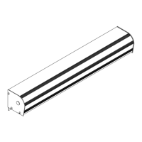
Figure 58
Fixed Sidelite
DN 0640
1/4 - 20 x 3/4” Whiz-Lock Screw
Slide Door
Washer
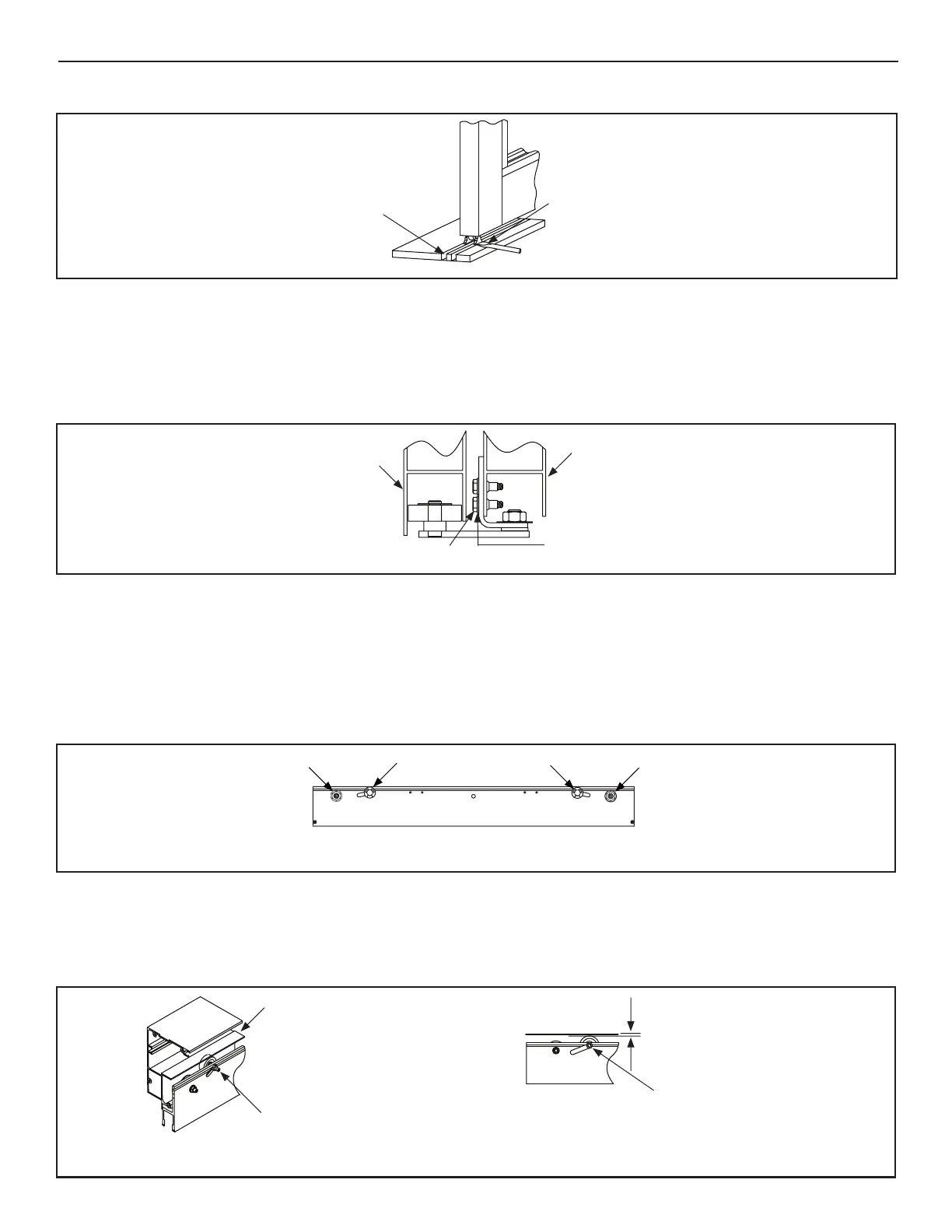
1. Raise or lower the Slide door by turning the Axle of the Hanger Roller clockwise with a 15/16” Open End Wrench.
a. The appropriate gap between the Boom Rail and oor is between 11/16 inch to 15/16 inch; with the nominal gap
being 7/8 inch.
2. Ensure the Leading Edge of the Slide door and Header are parallel.
Figure 59
DN 1044
55mm An -Rise Rollers
Hanger Roller
Hanger Roller
Hanger Roller Centers must be to the
RIGHT of their bolts.
1. Loosen (2) An-Rise Rollers located towards the middle of the Carrier.
2. Slide the An-Rise Roller up or down within the slot unl there is 1/64 inch to 1/32 inch gap between the Roller Wheel and
the Top Track. The Gap should be about the same thickness as a credit card.
DN 0633
An -Rise Track
Slide An -Rise Roller up in slot un l
a 1/64 inch to 1/32 inch clearance
is between the An -Riser Wheel
and the An -Riser Track.
1/64 inch to
1/32 inch
clearance
Insert 7/32” Allen Wrench
Figure 60
 Loading...