14 of 62
GT1175 Standard and Pocketed Slide Doors Installaon Manual; with Opus Controller www.NabcoEntrances.com
P/N C-00370 Rev 11-12-20
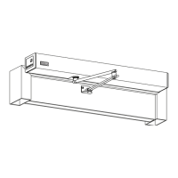
Figure 21
DN 0767
Y
48”
max
Y
Y
Y
Y
max
max
Y
SLIDE DOOR
SLIDE DOOR w/TRANSOM
Y
Y
36”
max
48”
max
Y
Y
48”
max
Y
Y
Note: It is recommended to countersink holes as required to ush the surface.
Note: It is recommended to drill tap threads for 1/4 inch anchors in a steel or aluminum structure.
Note: Do not overghten anchors to prevent deforming Jamb Tubes.
Use 1/4 inch diameter anchors with a minimum of 3 per Jamb Tube, maximum is 48 inches on center. Drill 1/4 inch diameter holes
in the face of Jamb and then countersink each hole.
DN 0418
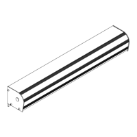
SLICK JAMB
1/4” Anchor
1/4” Anchor Hole(s)
POCKETED JAMB / VERTICAL TRANSOM
1/4” Anchor
1/4” Anchor Hole(s)
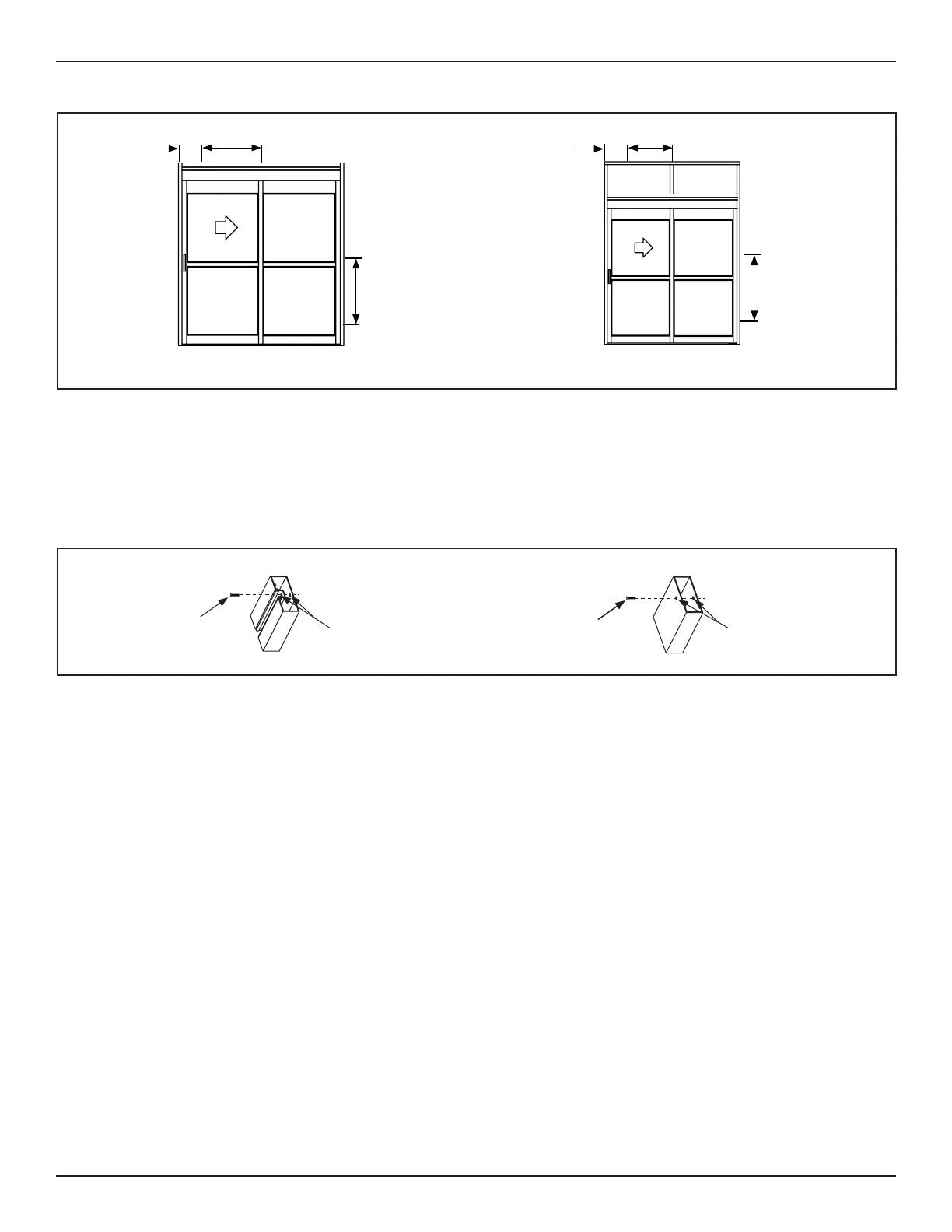
Figure 22
X
X
To prevent Header sag, use 1/4 inch diameter anchors or 3/8 inch threaded rods, with a maximum 48 inches on center. First
anchor maximum is 36 inches from each end of the Header. Drill 1/4 inch diameter holes inside the top of Header.
1. Aer the Frame has been installed, slide each Tie Rod up the Channel into each 3/8-16 Anchor located in the ceiling.
a. The 3/8-16 Anchor is used to securely fasten the Frame.
2. Go to the boom of each Tie Rod. Tighten the 3/8-16 Hex Nut and 3/8 inch Lock Washer to secure the Backing Plate.
3. Snap the Back Plate back into each Transom Vercal.
a. It may be necessary to use a rubber mallet to slightly tap the Back Plate into place.
b. Protect the surface of the Back Plate before hing it with a rubber mallet.
1. Go inside the Header. Locate the Pin wiring that is aached to the U30 Microprocessor Control, Main Harness.
2. Draw Pin wiring through a hole located at the side of Header and Jamb Tube. Connue to route wiring down the Jamb Tube.
3. Pull the Pin Wiring out, through the cut out.
4. Obtain (1) loose 5 Circuit Pin Housing from the Parts Box. Insert each Pin into the 5 Circuit Pin Housing accordingly:
a. 1 = Red, 2 = Orange/White, 3 = Blue, 4 = Green, 5 = Orange
 Loading...