11
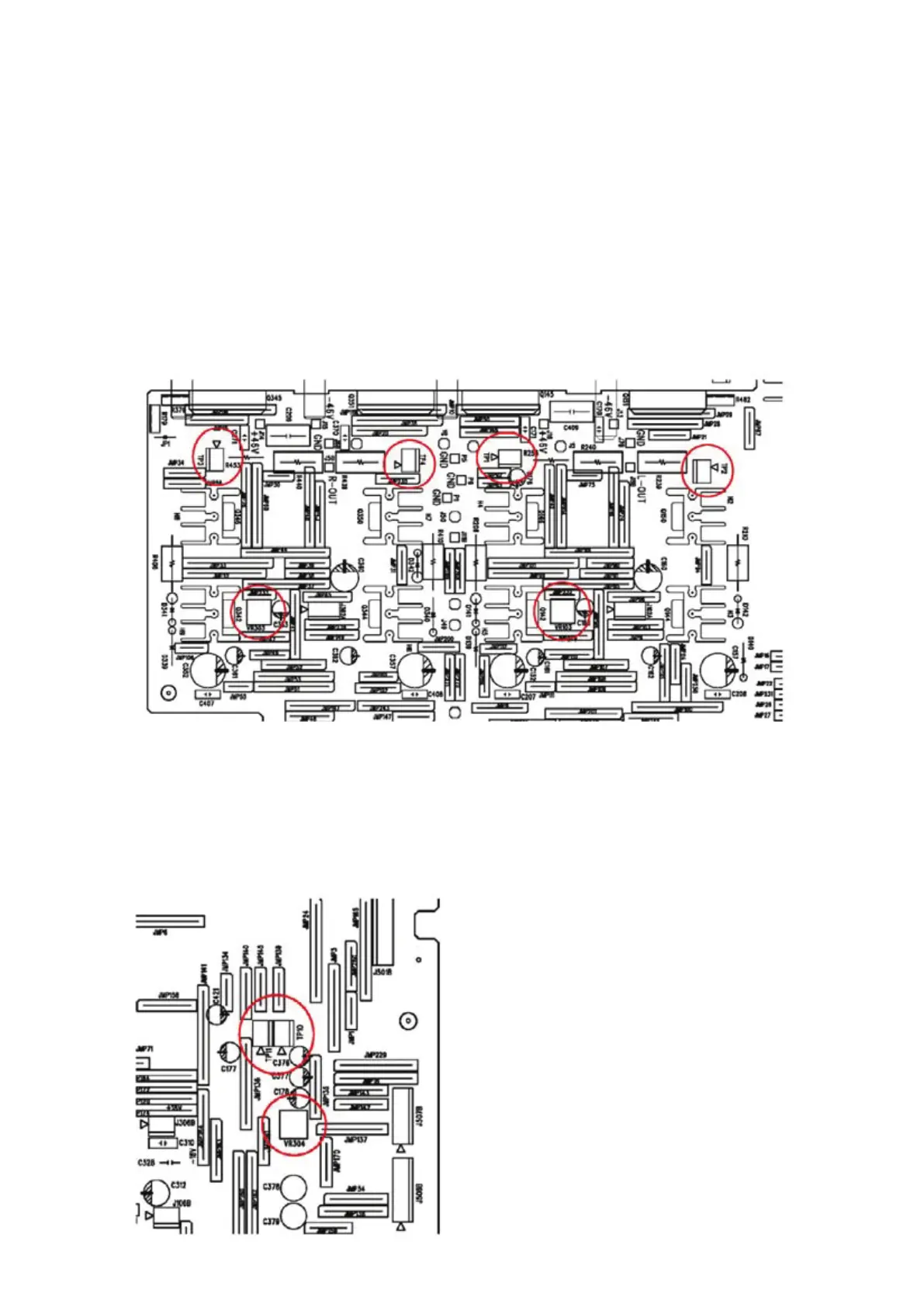
ADJUSTMENT POINT DIAGRAM
A. Idle Current adjustment
1. Turn on the unit without any input for 15 minutes
2. For left channel, adjust VR103
Voltage across TP1 & TP2 3 – 3.5mV
3. For right channel, adjust VR303
Voltage across TP3 & TP4 3 – 3.5mV
4. With the unit keep turning on, wait for another 15 minutes
5. Re-adjust VR103
Voltage across TP1 & TP2 3 – 3.5mV
6. Re-adjust VR303
Voltage across TP3 & TP4 3 – 3.5mV
B. ISC adjustment
1. Turn VR304 fully anti-clockwise,
2. Use 500mV, 1kHz sine wave, CD input, 4 ohm loading to both channels
3. Increase the output power of both channels to 8V
4. Slowly rotate VR304 clockwise until the voltage at TP10 is the same as TP11
5. Verify the output at 20kHz 8 ohm loading to both channels are larger than 21V, if not, repeat
step 1-4 again