24
ENGLISH FRANÇAIS
DEUTSCH
NEDERLANDS
ESPAÑOL
ITALIANO
PORTUGUÊS
SVENSKA
11. CD, DISC, TUNER Inputs: Connect to stereo analog outputs of audio components.
12. TAPE IN/OUT: Connect TAPE OUT to the analog recording component’s stereo analog
inputs, and TAPE IN to the analog recording component’s stereo analog outputs. Suitable
components would be cassette deck, CD-recorder, or auxiliary analog audio processor.
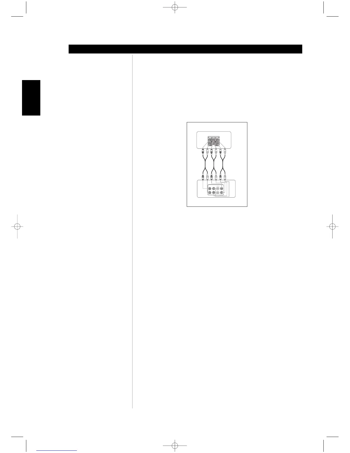
13. EXTERNAL 7.1 INPUTS: Connect to the corresponding analog audio outputs of a multi-
channel source component such as a DVD-Audio or multi-channel SACD player. There are
neither bass/treble controls nor other audio processing available for these inputs. (See figure
below)
14. IR IN/OUT: There are two 3.5mm IR OUT and one IR IN jacks. Connect to the
corresponding 3.5mm IR jacks (input to output and vice versa) of compatible infrared
receiver/transmitter components. Your custom installer or dealer can assist you in the
proper setup and configuration of the infrared cables and equipment interface.
15. +12 V TRIGGER OUT/IN: There are three configurable +12V trigger outputs. These +12V
TRIGGER OUT can follow the powered state of the M15. Use this 3.5mm mini-jack
connector to pass +12 volts at a maximum current of 50 milliamps to auxiliary equipment
such as a multichannel amplifier or subwoofer. Configuration of the trigger level and
duration for each output is through the M15's TRIGGER SETUP OSD menu.
The +12 V TRIGGER IN is setup in the TRIGGER SETUP OSD. When set to ON. a +12V
signal will turn on the M15 from standby.
Note: The centre conductor (hot) of the 3.5mm jack is the control signal. The outside
conductor (shield) is the ground return-path. Your custom installer or dealer can assist
you in the proper setup and configuration of the +12V TRIGGER OUT/IN interface and
cables.
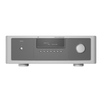
ABOUT THE M15
Identification of controls