Page 13
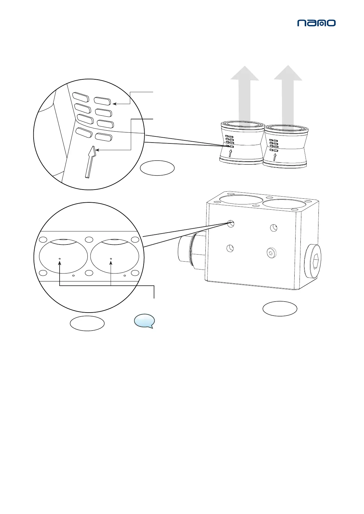
INLET VALVES
FLOW DIRECTION
ARROW
6. Insert new inlet valves into valve block ensuring ow direcon arrow is poinng as shown and the valve ridge details
cover the spill port. (See gures 4 & 5)
4. Remove inlet valves from valve block (push out). (See gure 3).
5. Discard old inlet valves.
SPILL PORT
VALVE RIDGE
DETAILS
7. Replace the 6x M8 socket head cap screws and 6x washers ghten at a torque seng of 20Nm.
(See gure 2)
NOTE: The spill ports are 1.5mmØ
holes within the valve block.
When service A is complete reset the dryer, refer to page 21.
8. SERVICE ‘A’ INSTRUCTIONS
MODELS: NDL-100, 110, 120, 130
INLET VALVE REPLACEMENT
IVK-130
Figure 5.
Figure 3.
Figure 4.


 To Next Page