Page 18
(Every 24,000 hrs or 4 Years)
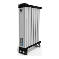
EXHAUST VALVE REPLACEMENT
O RING
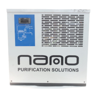
VALVE DIAPHRAGM
EXHAUST VALVE BODIES
SILENCER
FIXING NUT
M5 SOCKET HEAD
SCREWS
3. Remove the 8x M5 socket head
screws and the 8x spring washers and
remove the exhaust valve
bodies and diaphragms from the inlet
(boom) manifold.
(See Figure 2)
4. Replace the 2x diaphragms and 2x
exhaust valves from the service kit.
5.Replace the 8x M5 socket head
screws and spring washers and ghten
at a torque seng of 6Nm. Reaach
the 2x solenoid valves and 2x plugs.
(See Figure 2)
11. SERVICE ‘B’ INSTRUCTIONS
MODELS: NDL-100, 110, 120, 130
CVK-130 & EVK-130 & PVK-131
Figure 1.
Figure 2.
3
2
4
1
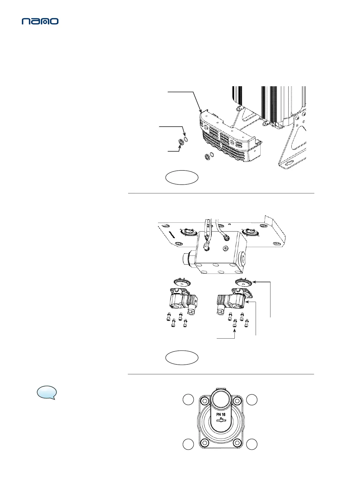
NOTE: correct valve screw
ghtening sequence shown.
1. Ensure the dryer is shutdown and
fully depressurised before aempng
any maintenance work. (See page 8-9)
2. Unscrew the silencer xing nut using
a 20mm pin spanner and remove the
O ring to release the silencer box from
the assembly.
(See Figure 1)
SILENCER
BOX
 Loading...