Page 22
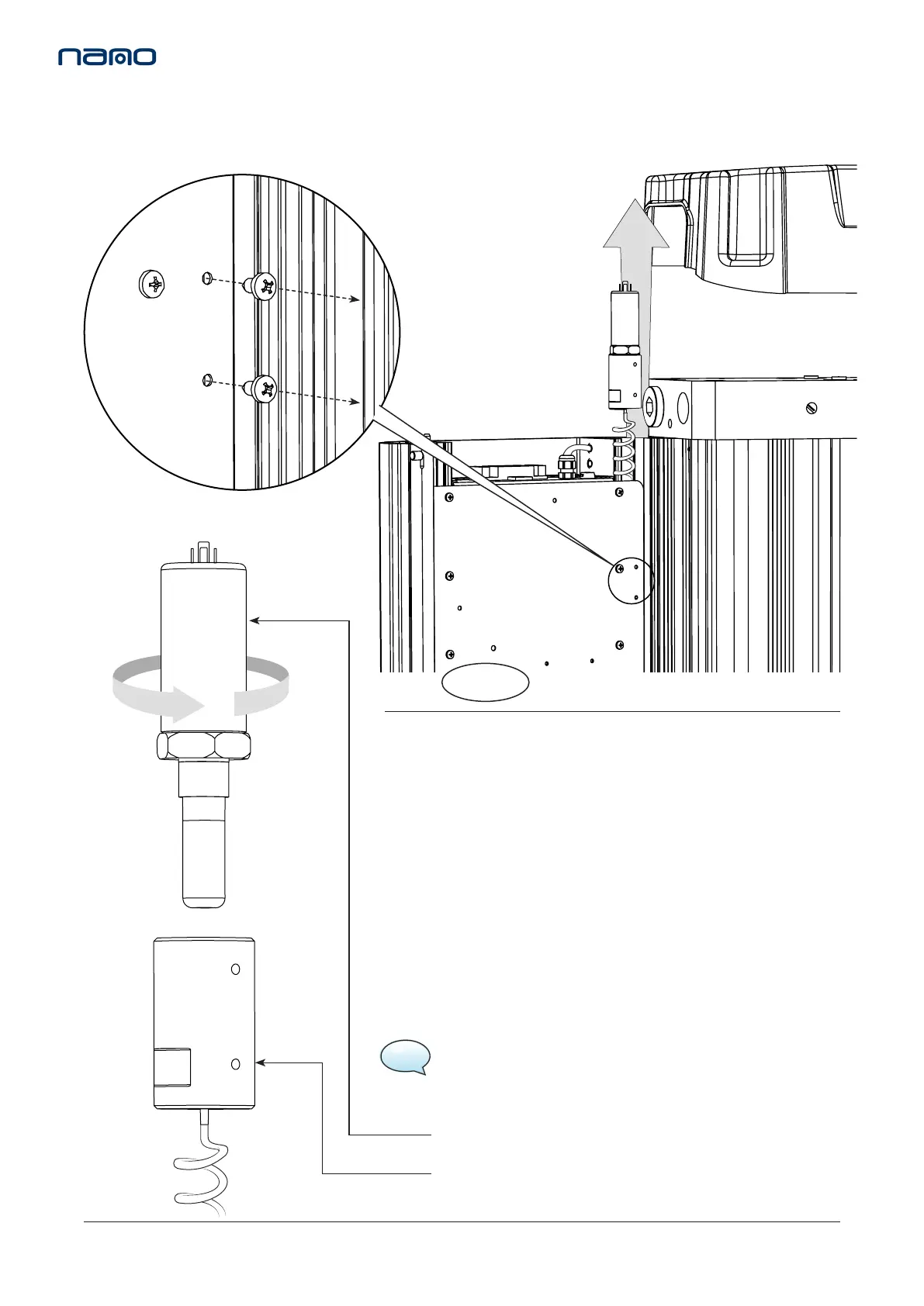
Figure 7.
6. Unscrew the dew point sensor from the sensor block and
replace with the new or re-calibrated sensor. (See Figure 7)
7. Reaach the new or re-calibrated dew point sensor and sensor block
assembly to the controller chassis plate using the 2x xing screws.
8. Replace the sensor plug and screw to complete the sensor assembly.
(See Figure 3 & 4)
9. Close the shroud and ensure the latches are in posion.
10. Replace the top cover and insert the 4x M5 screws. These screws
should be hand ghtened only. (See Figure 1)
DEW POINT SENSOR
SENSOR BLOCK
Figure 5.
5. Remove the 2x xing screws from the controller chassis plate and
release the dew point sensor assembly. (See Figure 5 & 6)
When service C is complete reset the dryer, refer to page 23.
13. SERVICE ‘C’ INSTRUCTIONS
DEWPOINT SENSOR REPLACEMENT
NSK-130
(Every 6,000 hrs or 12 months)
ES MODELS ONLY
Figure 6.
NOTE: Allow sensor to stabilise, this may take several hours.
 Loading...