Appendix B Hardware Configuration
NI 8352/8353 User Manual B-8 ni.com
Chassis Intrusion Switch Connector: JL1
JL1 is the chassis intrusion header. Attach the appropriate cable to be
informed of a chassis intrusion.
Figure B-11. Chassis Intrusion Switch Connector (JL1)
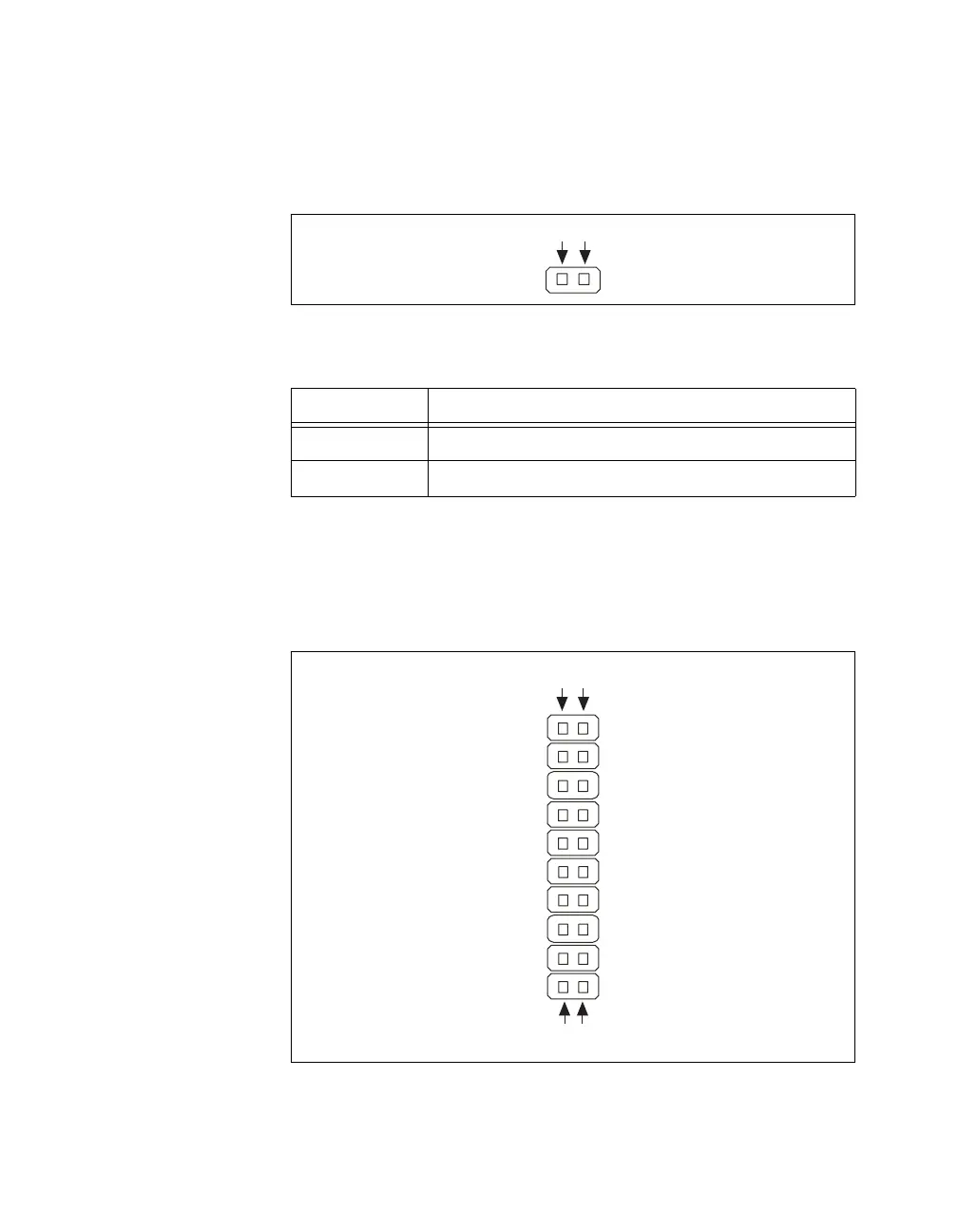
Front Panel Connector: JF1
JF1 contains header pins for various buttons and indicators on the control
panel at the front of the chassis. These connectors are designed specifically
for use with this chassis.
Figure B-12. Front Panel Connector (JF1)
Table B-1. Chassis Intrusion Switch Connector Signals
Pin Signal Name
1 CINTRU
2 GND
2
1
1
2
19
20
 Loading...


