Appendix B Specifications
© National Instruments Corporation B-5 cFP-20xx and cFP-BP-x User Manual
Cabling
Table B-1 shows the standard Ethernet cable wiring connections for both
normal and crossover cables.
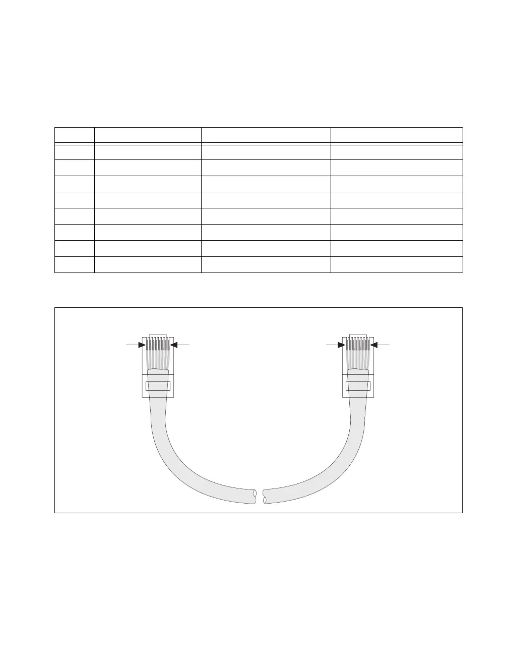
Figure B-1 shows the connector pinouts for FieldPoint Ethernet cables.
Figure B-1. Ethernet Cable Pinout
Table B-1. Ethernet Cable Wiring Connections
Pin Connector 1 Connector 2 (Normal) Connector 2 (Crossover)
1 white/orange white/orange white/green
2 orange orange green
3 white/green white/green white/orange
4 blue blue blue
5 white/blue white/blue white/blue
6 green green orange
7 white/brown white/brown white/brown
8 brown brown brown
Connector 1 Connector 2
pin 1
pin 1 pin 8pin 8
 Loading...