Chapter 3 Connecting Signals
DAQCard-700 User Manual 3-18 ni.com
To measure frequency, program a counter to be level gated and count the
number of falling edges in a signal applied to a CLK input. The gate signal
you applied to the counter GATE input is of a known duration. In this case,
program the counter to count falling edges at the CLK input while the gate
is applied. The frequency of the input signal then equals the count value
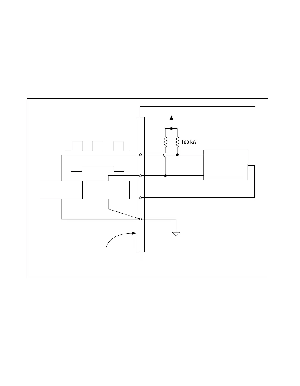
divided by the gate period. Figure 3-9 shows the connections for a
frequency measurement application. You could also use a second counter
to generate the gate signal in this application.
Figure 3-9. Frequency Measurement Application
The GATE, CLK, and OUT signals for counters 1 and 2 are available at the
I/O connector. In addition, the GATE and CLK pins are pulled up to +5 V
through a 100 kΩ resistor.
Signal
Source
I/O Connector
+5 V
19 DGND
CLK
GATE
OUT
Counter
DAQCard-700
Gate
Source
 Loading...