Chapter 4 Theory of Operation
DAQCard-700 User Manual 4-10 ni.com
The MSM82C54 contains three independent 16-bit counter/timers and one
8-bit mode register. As shown in Figure 4-5, counter 0 can be used for DAQ
timing, and counters 1 and 2 are free for general use. Counter 0 is free for
general use when EXTCONV* is being used to time the AI circuitry or
when the DAQ circuitry is not in use.
The MSM82C54 counter 0 uses a 1 MHz clock generated from the onboard
oscillator. The timebases for counters 1 and 2 can be supplied externally
through the 50-pin I/O connector. In addition, counter 1 can optionally
use the same onboard 1 MHz clock that is used for DAQ timing, which
facilitates synchronous operations. The counters in the MSM82C54 can be
diagrammed as shown in Figure 4-6.
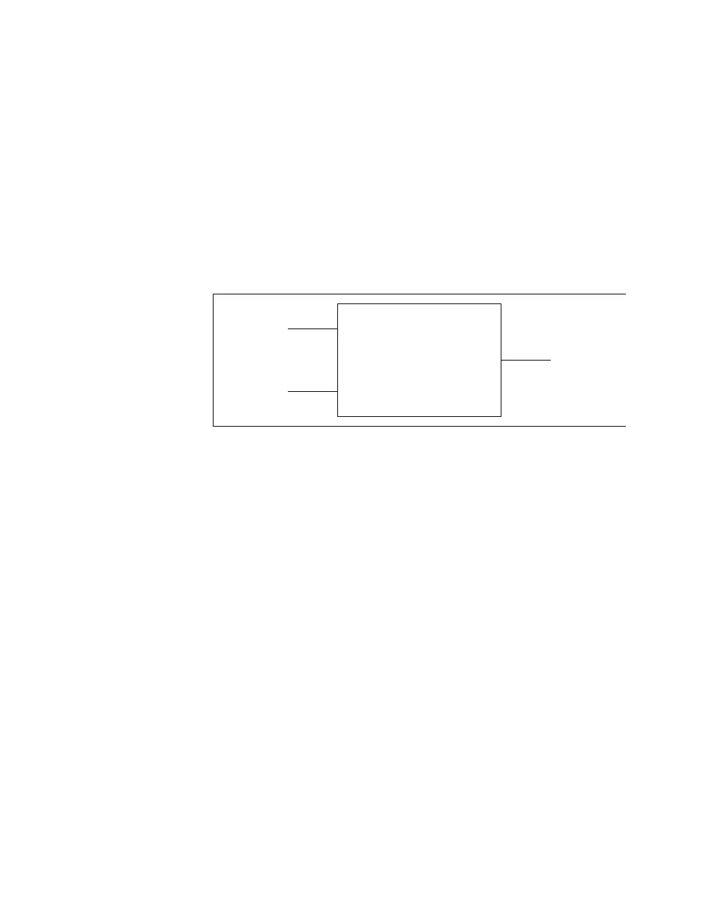
Figure 4-6. Counter Block Diagram
Each counter has a clock input pin, a gate input pin, and an output pin
labeled CLK, GATE, and OUT, respectively. The MSM82C54 counters are
numbered zero through two, and their GATE, CLK, and OUT pins are
labeled GATE N,CLKN,andOUTN,whereN is the counter number.
Counter
CLK
GATE
OUT
 Loading...