10 | ni.com | NI myDAQ User Guide
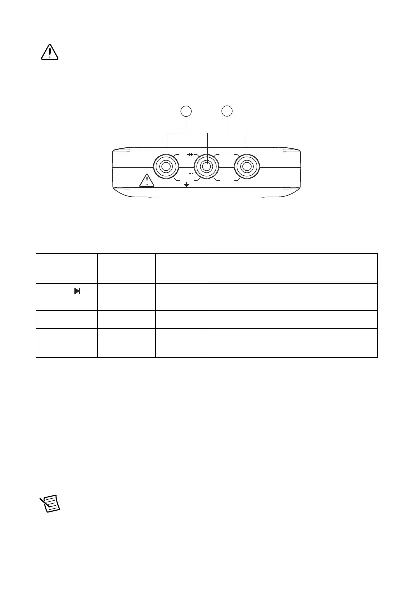
Figure 5 shows the DMM connections on the NI myDAQ. Table 2 describes these signals.
Caution 60 VDC/20 Vrms maximum. Do not plug digital multimeter probes into
circuits with Hazardous Voltages, such as wall outlets.
Figure 5. Connections for DMM Measurements
Connecting Analog Input Signals
When configuring the input channels and making signal connections, you must first determine
whether the signal sources are floating or ground referenced. The following sections describe
these two signal types.
Ground-Referenced Signal Sources
A ground-referenced signal source is connected to the building system ground, so it is already
connected to a common ground point with respect to the NI myDAQ device, assuming that the
computer is plugged into the same power system. Instruments or devices with nonisolated
outputs that plug into the building power system are ground-referenced signal sources.
Note Most laptop computers have isolated power supplies, and are consequently
not connected to the building ground system. In these cases, treat the analog input
signal as floating with respect to NI myDAQ.
1 Connectors for Voltage/Resistance/Diode/Continuity
2 Connectors for Current
Table 2. DMM Signal Descriptions
Signal
Name
Reference Direction Description
HI (VΩ ) COM Input Positive terminal for voltage, resistance,
and diode measurements
COM — — Reference for all DMM measurements
HI (A) COM Input Positive terminal for current measurements
(Fused: F 1.25 A 250 V Fast-Acting)
1
2
HIHI COM
A
MAX
0 V
20 Vrms
MAX
 Loading...